6 Measurements and Math Functions
222 InfiniiVision Oscilloscopes User’s Guide
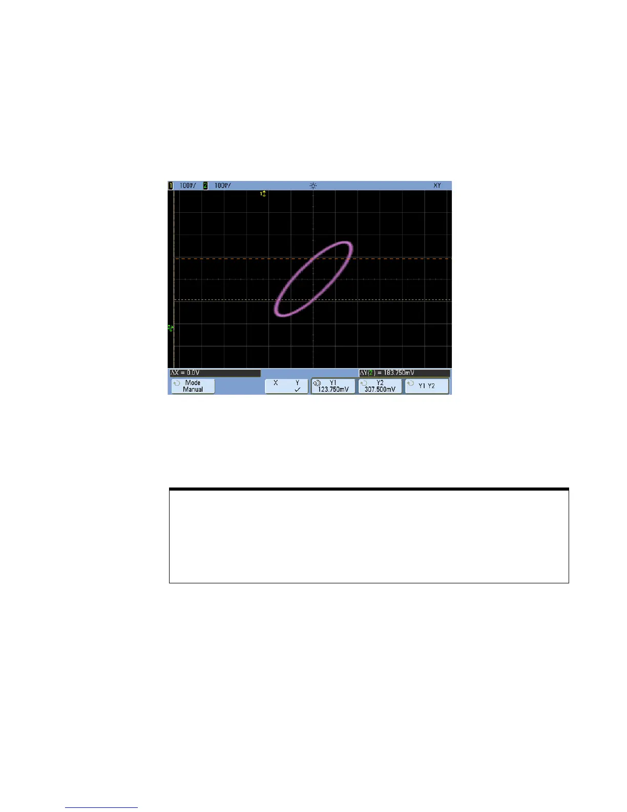
6 Move the Y1 and Y2 cursors to the intersection of the signal and the Y axis. Again,
note the Y value.
C
URSORS SET TO CENTER OF SIGNAL
7 Calculate the phase difference using the formula below.
= sin
second Y
first Y
--------------------------
1.031
1.688
-------------
; = 37.65 degrees of phase shift=
Z-Axis Input in XY Display Mode (Blanking)
When you select the XY display mode, the time base is turned off. Channel 1 is the X-axis input,
channel 2 is the Y-axis input, and channel 4 (or the External trigger on 2-channel models) is the
Z-axis input. If you only want to see portions of the Y versus X display, use the Z-axis input. Z-axis
turns the trace on and off (analog oscilloscopes called this Z-axis blanking because it turned the
beam on and off). When Z is low (<1.4 V), Y versus X is displayed; when Z is high (>1.4 V), the
trace is turned off.

 Loading...


