Installer manual AlphaVision ML Rev. 3.60 01-01-2015 17
Explanation about jumpers, LED’s and fuses on the AlphaVision ML
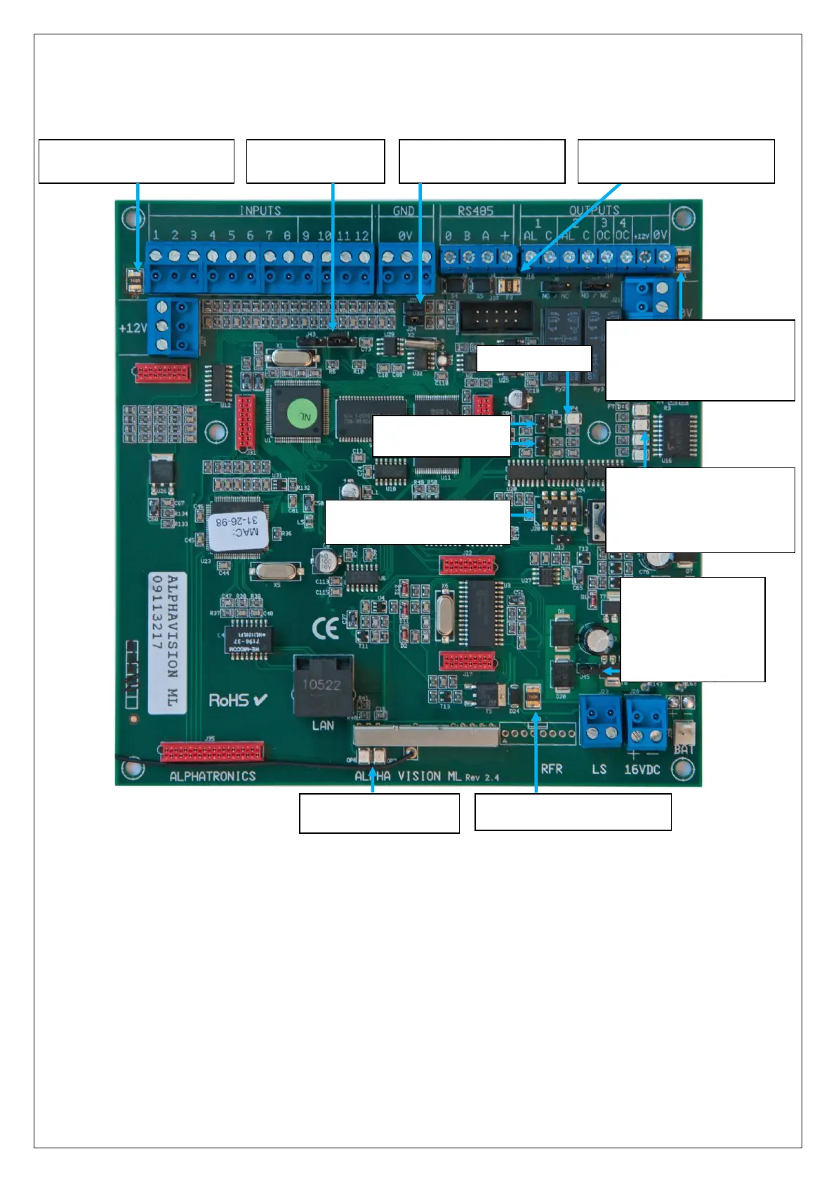
The AlphaVision ML board is equipped with several jumpers, LED’s and fuses. In the drawing below this is
explained.
Jumper settings
J1 - Watchdog OFF, short-circuit the 2 pins during firmware flash via RS-232 (not LAN) with Renesas tool
J2 - Reset pin, can temporarily be short-circuited to reset the main board.
J43 - Flash position (2 left pins connected) and Run position (2 right pins connected)
J44 - Write Protect position (2 left pins connected) and Write Enable position (2 right pins connected)
J24 + J25 – Pull-up resistors RS-485 bus (should always be present)
J45 – place jumper for NiMH battery pack (synthetic cabinet) remove for lead acid battery (metal cabinet)
Voor het flashen van
nieuwe firmware
Voor intern gebruik.
Niets aansluiten
8 Be12 hardwired inputs
EOL
Bus
(
(Alphn)
KA
elde ingangen
EOL (End of Line)
Dipswitch 1 (left) to
Dipswitch 4 (right)
LED 1: LAN transceiver
LED 2: GPRS dialer
LED 3: IP message in Buffer
LED 4: RUN
OP6: LAN Activity
OP7: Link
J45: charging circuit;
connect Alarm output
AL
1 +
AL2
(Potential free contact NO/NC,
selectable by jumpers below)
OC3 (200mA) (Open
OC4 (200mA)
collector)
(
OC
(Alphn)
both pins for NiMH
batterypack
J24 and J25, RS-LAN
connection
resistors
F5 polyfuse
1,1A (for +12V out)
J43: Flash / Run
J44: Write protect
Watchdog LED
us
(
(Alphn)
F3 polyfuse
500mA (for RS-485 bus)
Polyfuse
F1 =500mPower supply
n 2) F7 en F8=200mA (OC3
and 4)
J(1): Watchdog uit
J(2): Reset jumper