Installer manual AlphaVision ML Rev. 3.60 01-01-2015 18
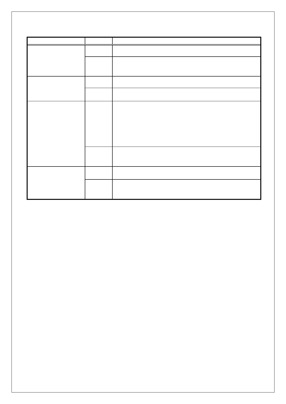
Dipswitch settings on the AlphaVision ML
When dipswitch 1 is set to ON and the AlphaVision ML is powered
up, the default (factory) settings will be programmed into the
AlphaVision ML.
‘Normal’ position. The programmed IP settings are valid.
The AlphaVision ML can be reached through IP address
192.168.0.48 and web server port 80.
Remote service via IP is entirely blocked regardless of the settings
in the programming (Installer menu/Dialer/Remote Service/IP
configuration/Connect via IP – YES/NO). When trying to establish
a IP connection the AlphaVision ML will not answer. This is the
most secured position.
Warning: for a certified installation dipswitch 3 must be set to
OFF!
Remote service is possible depending on the settings in the
programming (Installer menu/Dialer/Remote Service/IP
configuration/Connect via IP – YES/NO).
Dipswitch 4 should always be in the OFF position.
If Dipswitch 4 is put in the ON position the internal tamper switch
on the main board is bridged. Do not forget to put the dipswitch
back to the off position when closing the cabinet !
Connecting the AlphaVision ML to a LAN connection
The AlphaVision ML is equipped with an integrated IP dialer for alarm reporting to a central station. Connect
a network cable between the LAN connector of the AlphaVision ML print and a free network (LAN) port on
the modem / router of the ISP (Internet Service Provider). Make sure the LAN connection is made directly
on the modem /router of the ISP and not on a switch somewhere in the network.
Using the LAN connection, the AlphaVision ML can transmit alarm signals to a central station and the
installer can connect to the control panel to perform remote service and programming.
Connecting the AlphaVision ML to a analog (PSTN) telephone line
The AlphaVision ML can be extended with a plug-on analog (PSTN) dialer. The PSTN dialer is equipped with a
priority circuit. Connect the incoming telephone line to the telephone line connection (LINE) of the dialer.
Connect all telephone devices to the output connector of the priority circuit which is marked with “SET”. For
both connectors (LINE and SET) only the two middle wires are used. By connecting the priority circuit
correctly the dialer will always have access to the telephone line even if the line is engaged.
Connecting hard-wired inputs to the AlphaVision ML control panel
The AlphaVision ML has 12 inputs onboard for the connection of 12 hard-wired zones. The inputs can be
programmed as N.C. (Normally closed), NO (normally open) or EOL (end-of-line) inputs (choice of NC =
normally closed or normally open = NO).
The supply voltage for the 12 hard-wired zones can be obtained through the +12 V and 0V terminals on the
main board. All zones (1 through 44) have a default programming set to "not active".
If more than 12 hard-wired inputs are necessary this can be done by using zone expansion modules, the
maximum number of zones is 44. The wired expansion modules are available in two versions: Input module
+ open collector (o.c.) outputs (art.nr. 009831) and an I/O modules include power supply and outputs in a
metal cabinet (art.nr. 004312). Besides hard-wired extension module a wireless extension module is