Installer manual AlphaVision ML Rev. 3.60 01-01-2015 23
Connecting an external Proximity Reader to the AlphaVision ML
The AlphaVision ML can be extended with 1 external proximity reader. Using the proximity reader the
system can be totally (TOTAL) armed or disarmed and also provide simple access control for personnel.
When connecting an external proximity reader, the AlphaVision ML system must always be equipped with a
LCD/Proximity keypad to be able to enroll proximity tag’s.
The Proximity Reader is suitable for both indoor and outdoor installation, because the electronics of the
reader is fully encapsulated. This Proximity Reader is protected against harsh environments. The proximity
reader communicates with the control panel through the RS-485 bus.
►!: The external proximity reader can only be used if a LCD/Proximity keypad is also installed.
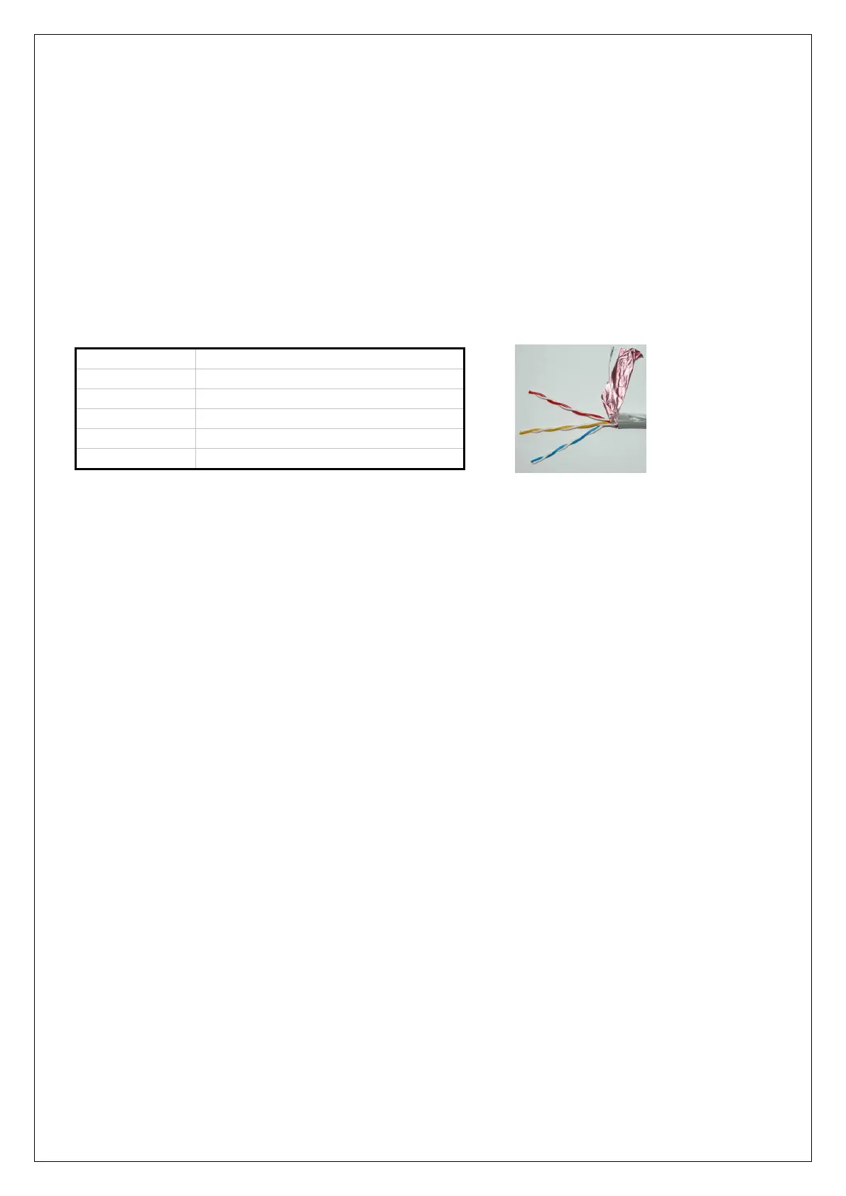
The Proximity Reader is delivered with a 2m cable containing the following color codes:
A-line RS-485 bus communication
B-line RS-485 bus communication
►! The standard cable consists of 5 wires. The red and yellow wires are twisted with a white wire with a
red or yellow mark. During the production, the white wire with blue mark, which belongs to the blue wire is
removed. The blue wire is an open collector output (max 100mA) which is activated when presenting a valid
tag combined with the level associated to the proximity tag (user code) and depending on the system status.
The blue wire can thus be used to activate a electric door strike for simple access control.
►! The proximity reader should NOT be mounted on a metal surface! If this is unavoidable, use a spacer
plate RDM-BACK (art. 007913) between the mounting location and the Proximity Reader. The spacer creates
a distance of about 1cm between the proximity reader and the metal surface. If the distance between an
metal surface and the proximity reader is too small, the reading distance will be influenced!
►! The Proximity Reader must also be enabled in the programming (Installer menu / System options /
Configuration / Proximity reader -YES)
Address settings for the Proximity Reader
The Proximity Reader (PR) does not have a DIP switch to set the address, but is factory-supplied with
address 1. The addressing of the Proximity Reader does not affect other equipment on the RS-485 bus. It is
therefore allowed to connect both a proximity reader set to address 1 as well as a keypad set to address 1
and an I/O module set to address 1. You can only connect a maximum of 1 Proximity Reader to the
AlphaVision ML.
Visualizing address settings of the proximity reader
The address which is set in the PR is easily visible. The PR has a 2-color LED, green or red steady or blinking.
Power up the PR. During the first seconds after power-up the LED will flash red several times and then be off
for several seconds. The number of times that the red LED flashes corresponds to the programmed address.
After displaying the address the red LED will light continuously.
►!: The Proximity reader must always be set to address 1.