Installer manual AlphaVision ML Rev. 3.60 01-01-2015 24
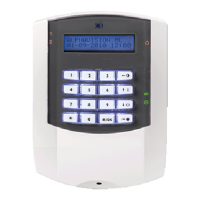
Changing address settings of the proximity reader
If the address is not set to "1", it can easily be changed. Power down the PR and then reconnect the power
again. The PR uses the integrated LED to show the current address. Present a random proximity tag to the
PR as often as the desired address (1 time for address 1). Every time the tag is presented during address
setting the LED will flash green. After setting the desired address check that the address is correct according
to the ‘Visualizing address settings’ chapter.
OC output on the proximity reader
The proximity reader is equipped with an open collector (OC) output (blue wire) that can provide a
maximum current drain of 100mA. When presenting a valid proximity tag the OC output is activated for 3
seconds depending on the level of the proximity tag (user code) and the status (on or off) of the system. A
buzzer can be connected directly to the OC. output. The negative side of the buzzer is connected to the OC
output and the other side of the buzzer is connected to the +12 V.
For controlling an electric door strike for simple access control the OC output can be connected to a relay.
With this relay, the (independent) power supply to the electric door strike can be operated. Always connect
a diode in anti-parallel over of the relay coil! An electric door strike should preferably be installed with its
own power supply and not be fed from the AlphaVision ML power supply!
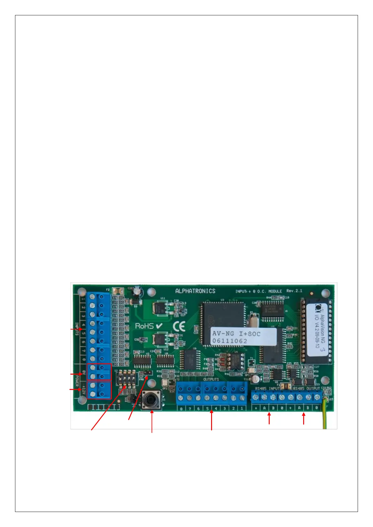
Connecting a AlphaVision Input + 8OC module
An Input + 8 o.c. module communicates with the control panel through the RS-485 bus. To connect an Input
+ 8 o.c. module to the control panel use the RS-485 INPUT terminals on the module and the RS-485
terminals on the control panel. The data communication terminals (A and B) and power (+12 V and 0V)
should be connected accordingly.
Using the dipswitch on the Input + 8 o.c. module, set the module to the first free address. See Appendix F
‘Expansion module address settings’ for the correct settings.
Dipswitchs
Incoming RS-485
(from control panel)
Reset pin
Tamper switch
O.C. outputs 1 - 8
Max. 100mA per output
Tw0 +12VDC
for detectors
Two 0V terminals
for detectors
Zone Inputs
1 - 8
Outgoing
RS-485
The AlphaVision Input + 8 o.c. module has 8 hard-wired INPUTS and 8 open collector (transistor) OUTPUTS.
The open collector outputs 1 through 4 are linked to the 4 outputs on the AlphaVision ML control panel.
Activation of the open collector outputs 1 through 4 are synchronized with outputs AL1 to OC4 on the
AlphaVision ML control panel. Output AL1 on the AlphaVision ML runs concurrently with output 1 of the