Installer manual AlphaVision ML Rev. 3.60 01-01-2015 19
available for connecting wireless zones. How to connect the expansion modules is explained further on in
this manual.
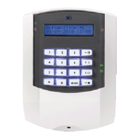
Inputs with EOL
If hard-wired zones are connected in the end-loop-resistance principle
(EOL, end-of-line) there is continuous monitoring if the cable between
the control panel and the detector is still intact. At the end of the cable,
in the casing of the detector or magnetic contact, a 1k8 resistor placed in
series with the input. Over the alarm contact of the detector a 10k
resistor is placed. Over the tamper contact a resistor is usually NOT
placed. Optionally a 39k resistor can be placed over de tamper contact.
Detector with EOL resistors
►! Alphatronics has magnetic contacts with built-in EOL (end of line) resistors!
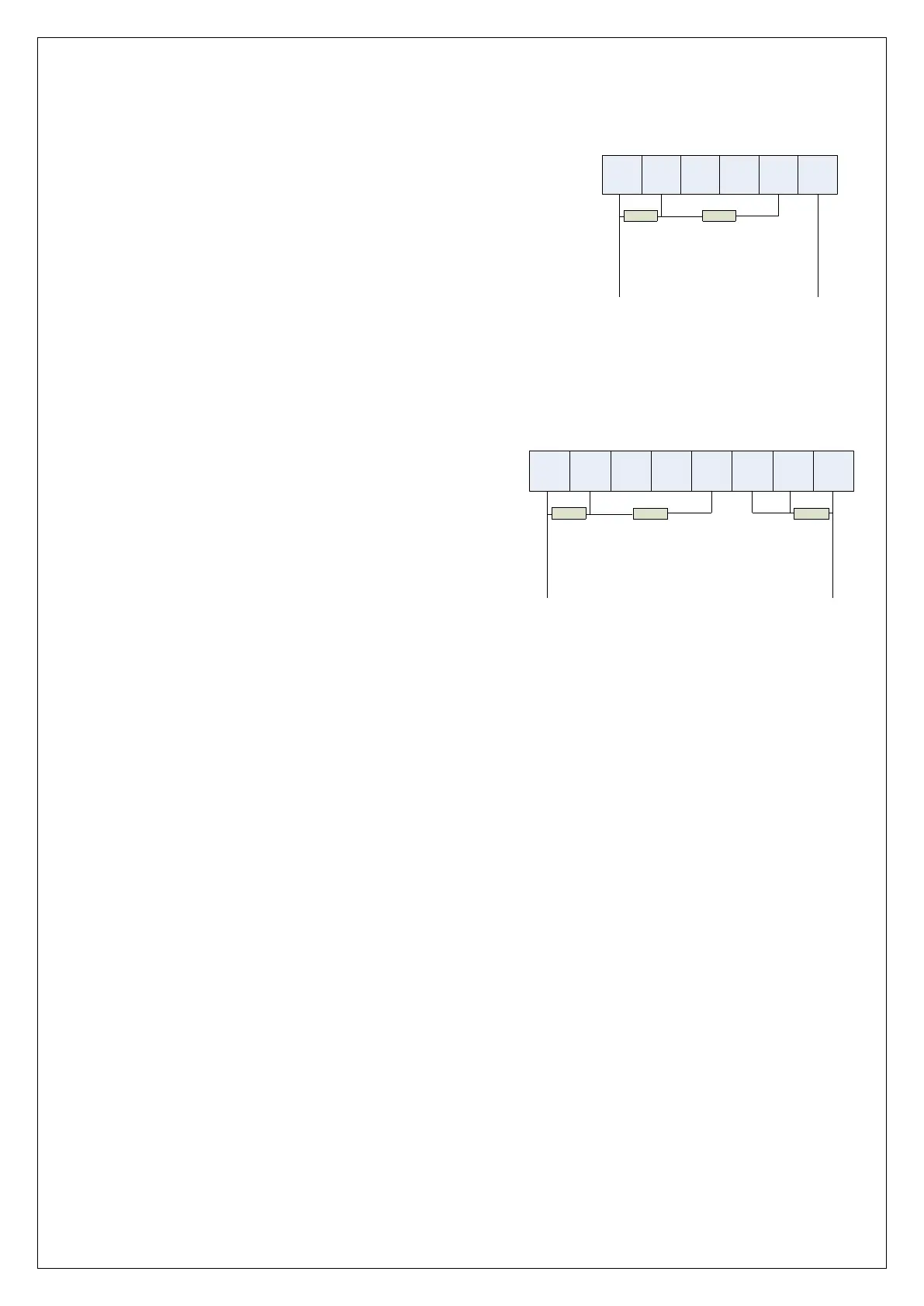
The 39k resistor, which was previously used (but not required)
for tamper, can be used from software V3.0 and above in the
AlphaVision ML to detect masking (usually called "anti-
masking"). Masking detection can be set per zone and is set
by choosing the zone characteristic "EOL NC antimasking" or
"EOL NO antimasking". Make sure that the 39k resistor is
installed over the masking contact in the detector. When the
detector is idle the loop resistance is 1k8. If the detector
detects masking (blocking the detector so a anti-masking alarm
occurs), then the loop resistance is 1k8 + 39k = 40k8. If also
an alarm occurs then the loop resistance is 1k8 + 10k + 39k = 50k8
Detector with EOL + AM resistors
►! From firmware version 3.2 and above various EOL resistor values can be connected
Connecting outputs on the AlphaVision ML
The AlphaVision ML control panel has four outputs. Outputs 1 and 2 (terminals AL and C) are floating relay
contacts (max. 30VDC/750mA), outputs 3 and 4 (terminals OC3 and OC4) are open collector outputs (max.
200mA).
Relay outputs
The potential free relay contacts (Output 1 and 2) may be connected as normally open (NO) or normally
closed (NC), depending on the position of J8 and J15 dipswitches. If connected as normally open (NO), in idle
state there is no connection between the AL and C terminal of that relay output. If an alarm occurs then the
relay contact will close and there will be a connection between the AL and C terminal.
Open Collector outputs
Outputs 3 and 4 are open collector (OC) outputs, both have maximum load of 200mA. The open collector
output should be seen as a transistor switch, which when activated the output is pulled to ground (0V). In
the deactivated state, the output is high impedance.
When the o.c. output is used to activate a LED for status purposes, a current limiting resistor in series with
the LED should be included. The cathode side of the LED is connected to the O.C. output and the anode side
should be connected through a series resistance (for instance 1K2) to the 12 V.
+ 12V 0VALARM TAMPER
1K8
10K
INPUT 0V
+ 12V 0VALARM TAMPER
1K8
10K
INGANG 0V
MASKING
39K