Installer manual AlphaVision ML Rev. 3.60 01-01-2015 22
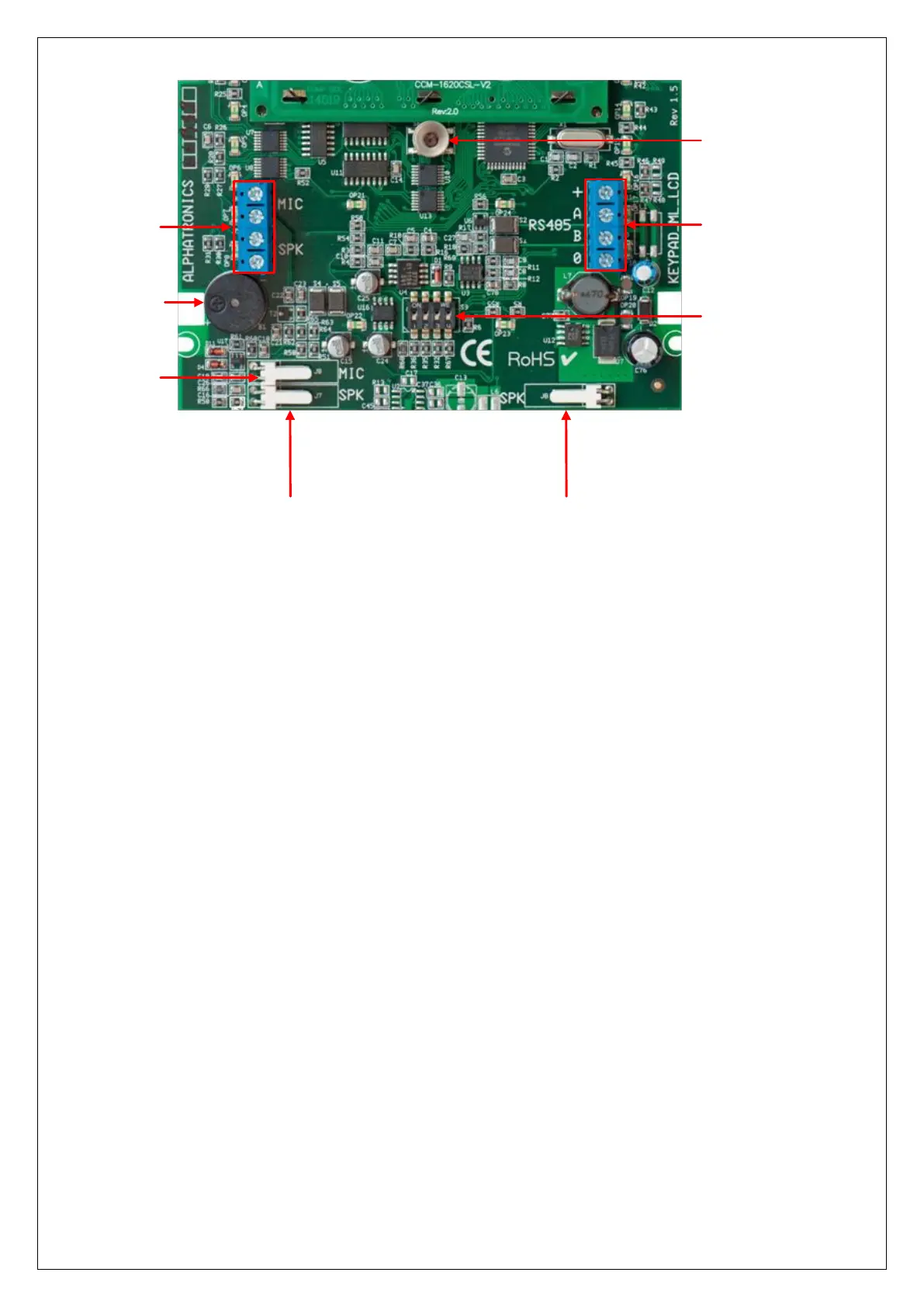
RS-485 bus
connection
Tamper switch
Dipswitchs
Speaker connection Speaker connection
Speech board
connection
Buzzer
Microphone
connection
When a LCD keypad is only connected to the 0V and +12V, the following will appear in the display:
-ML-LCD V1.2-
-->1
The "-> 1" indicates that the keypad is set to address 1. In this way you can check that all keypads are set to
the desired address. When powering up the system again the display of each keypad will briefly show this
message in the LCD display.
All keypads also contain 4 additional terminals (MIC and SPK) on the PCB, these are the connections to the
speech plug-on board. One (1) keypad can be equipped with speakers and microphone (art.nr. 004128). The
two terminals with the text 'SPK' must be connected to 'SPEAKER' terminals of the speech plug-on board.
The two terminals with the text ‘MIC’ must be connected to the ‘INPUT’ terminals of the speech plug-on
board.
Connecting LED keypads to the AlphaVision ML
The AlphaVision ML can also be equipped with a LED keypad, currently there are two brands of LED keypads
that are supported: the Key-7 SA840-AXX and the Roger PRA80XX. Both keypads can work as a normal “LED
keypad” or as a “last door” keypad. A “last door” keypad is used to stop the exit delay and to start the entry
delay. The advantage is that if the keypad is placed outdoors the LCD keypad can only be reached by first
starting an entry delay time through the LED keypad outside. It is not possible to enter the building through
the front door and tampering with the dialer of the control panel. If the exit time is stopped outside on the
LED keypad, people that might be hidden in the building do not have the time between exiting the building
and the expiration of the exit time to tamper with the system.
For both keypads a separate manual is available how to connect the keypad to the AlphaVision ML panel.