Installer manual AlphaVision ML Rev. 3.60 01-01-2015 26
The I/O module also has a speaker output (LS), where a 4-8 ohm speaker can be connected. The speaker
output on the I/O module is driven synchronously with the LS output on the AlphaVision ML main board.
Depending on the programming in the AlphaVision ML an alarm will activate the LS output of the I/O
module. When a fire alarm occurs a different slow whoop sound is generated by the LS output.
Mains failure, low battery and tamper of the I/O module is passed onto the AlphaVision ML control panel.
Using the ‘Information present’ menu on a keypad information is given over which I/O module has created
an event.
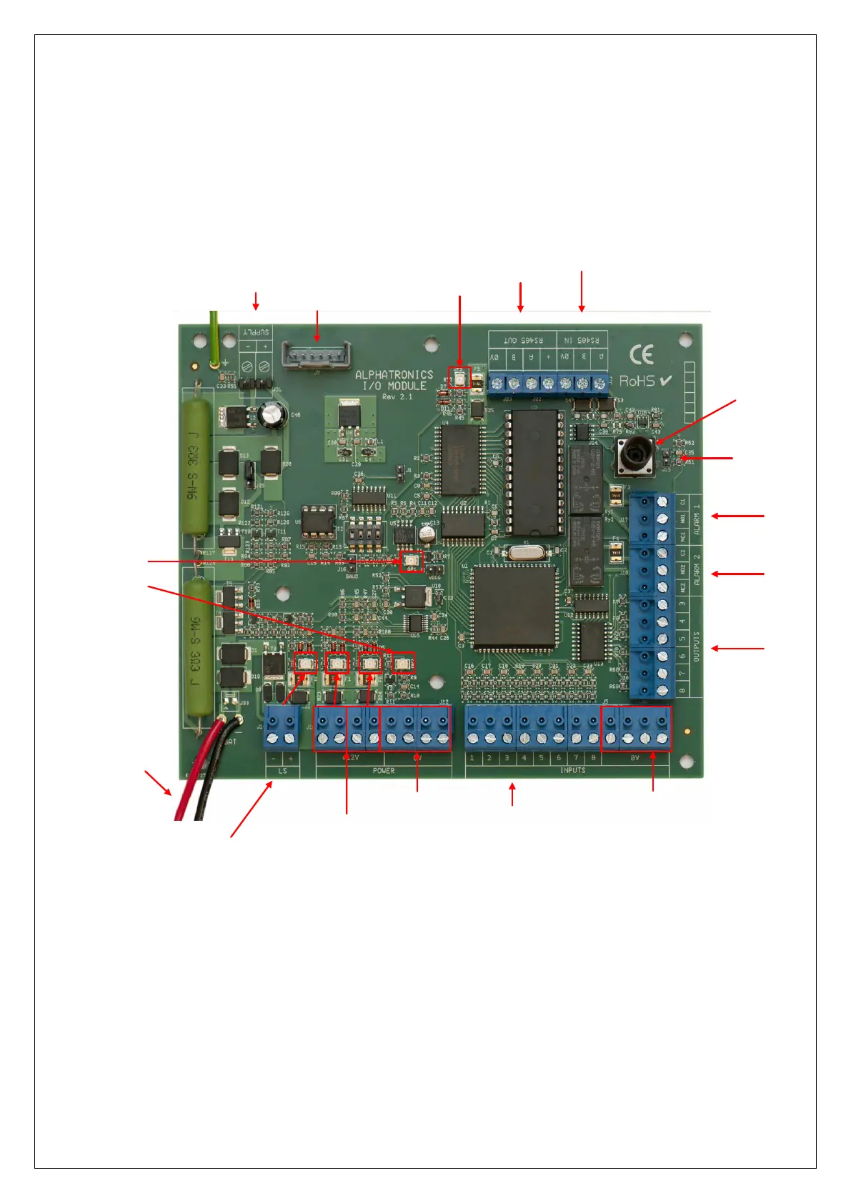
Incoming RS-485 bus (from control panel)
Outgoing RS-485 bus incl. Power supply
Power supply 15VDC
BATTERY conn.
(7Ah / 17Ah)
Ingang 1 t/m 8
Luidspreker aansluiting
met bijbehorende LED
(kortsluit indicatie F2)
Header for override
TAMPER switch
TAMPER switch
2 stuks +12VDC aansluitingen
met bijbehorende LED
(kortsluit indicatie F1 en F6)
0V aansluitingen
ALARM 1
Relay
output
ALARM 2
Relay
output
ALARM 3 - 8
Open Collector
outputs
RS-485 bus
communication LED
Watchdog LED
LED short-circuit Polyfuse F5 outgoing RS-485 bus
0V aansluitingen ten behoeve
van detectoren
Not used
By placing a jumper over the J15 pins the tamper switch of the I/O module can be bridged. In 'normal' use
this is not recommended. A tamper message will not occur if the casing is opened and the J15 pins are
bridged.
►! On the RS-485 (IN) terminal blocks the +12V terminal is missing. An I/O module i s equipped with its
own power supply. The RS-485 (OUT) terminal blocks contain 4 terminals including a +12V output. Do not
connect the incoming +12V to the I/O module, only 0V, A and B.
►! The address setting of the Input + 8 OC module is identical to the I/O module and is different than
the address settings of a keypad, see appendix F “Expansion module address settings”.