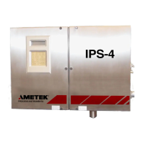
5-18 | IPS-4 Dual Bench (UV / IR) Analyzer
13. For applications with heated Sample Systems:
Apply power to the Sample and Vent Line circuitry.
Close the Oven Heater fuse to apply power to the Oven Heater
temperature-control zone circuitry.
14. Open the Vent Line Shut Off valve (in the Oven/Sample System En-
closure). Open the Sample Line Shut Off valve to allow sample fluid
into the sample system.
15. Close and secure the Electronics Enclosure doors, and allow the ana-
lyzer to warm up to operating temperature and stabilize. This could
take up to 2 hours if the sample system has cooled completely.
16. Zero and Span (if applicable) the analyzer.
17. Change the analyzer back to Measure mode (from the Calibration
screen, select Start measure and press ENTER). Press the HOME soft
key to return to the HOME screen.
18. Adjust the Aspirator Pressure Regulator to achieve normal operating
flow rates, as indicated on system Final “As-Built” drawings. The Flow
Indicator (if used) should be in the centre of the meter for an optimal
flow rate.
The procedure is complete.

 Loading...


