11-2 Getting Started Vector Voltmeter, Option 15
11-2 PN: 10580-00289 Rev. K Vector Network Analyzer MG
11-2 Getting Started
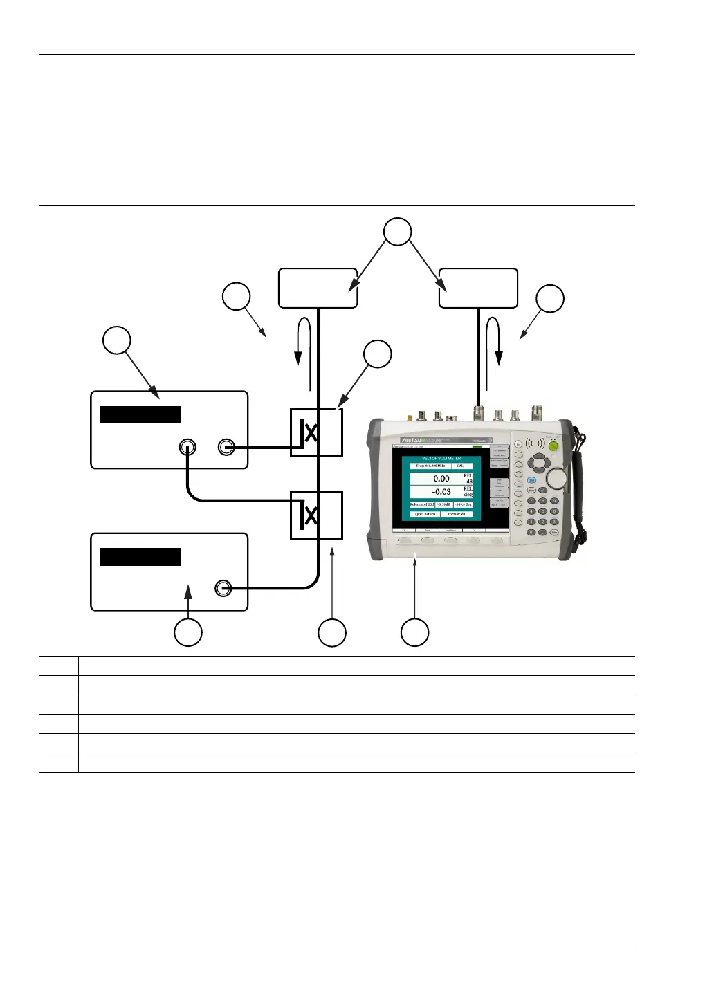
Figure 11-1 shows a block diagram comparison of the test configuration for the Vector
Voltmeter instrument method (left) and the Vector Network Analyzer (right) when used for
an S
11
measurement. The Vector Network Analyzer (when equipped with Option 15) contains
not only the Vector Voltmeter receiver, but also the signal source and couplers that are
necessary for conducting both 1-port and 2-port measurements at a selected CW frequency.
While phase sensitive cabling is used primarily in lower frequency applications that are
typical in air navigation systems such as VOR (VHF Omnirange), the Option 15 software
VVM procedures are applicable for the entire frequency coverage of the Vector Network
Analyzer
1VNAMaster
2 Couplers
3 Signal Generator
4 Vector Voltmeter
5S
11
Reflection Measurement
6 DUT (Device Under Test)
Figure 11-1. Vector Voltmeter within VNA Master
1
2
4
5
2
3
5
6
Vector
Voltmeter
Signal
Generator
DUT DUT
S
11
S
11
VNA Master