4-6 Waveguide Considerations VNA Measurements
4-14 PN: 10580-00289 Rev. K Vector Network Analyzer MG
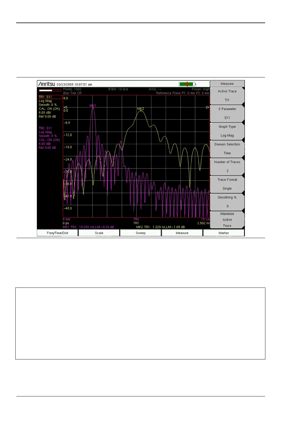
Measurement Readout and Interpretation
In the Distance Domain, the VNA Master includes waveguide dispersion correction to
account for different propagation speeds of signals in the waveguide. Dispersion correction is
not applied in Time Domain. The S
11
measurement of a 15 cm shorted waveguide section
(Figure 4-12) shows how dispersion compensation improves distance domain resolution.
Trace TR1 (yellow trace) is in the time domain without dispersion correction. Trace TR2
(purple trace) is in the distance domain. Peaks and troughs are better defined in the distance
domain (TR2) than in the time domain (TR1). Note that the distance domain response is
shown as One-Way, whereas the time domain plot is shown as Round-Trip.
Figure 4-12. S
11
on 15 cm Shorted Waveguide Section
Note
Figure 4-12
In the electronic (PDF) file of this user guide, the traces are shown in color, and are
therefore easier to distinguish.
In the printed grayscale image, Trace 1 (TR1) is smoother than Trace 2 (TR2).
Both traces begin at the low end of the frequency range at approximately –35 dB.
TR1 (time domain) peaks at 1.329 ns and –1.69 dB as shown by Marker MK2.
TR2 (distance domain) peaks at 15.293 cm and –0.29 dB as shown by Marker
MK1.