5-9 Distance-To-Fault (DTF) Field Measurements
5-16 PN: 10580-00289 Rev. K Vector Network Analyzer MG
12. Press the Freq/Dist function hard key and use the Stop Dist soft key to enter the Stop
Distance. Make sure that the Stop Distance is smaller than Dmax (refer to “DMax”
on page 5-17).
13. Press the Shift key, then the Calibrate (2) key.
14. Press the Start Cal soft key and perform a 1-port OSL calibration at the instrument
connector or at end of the extension cable. Follow the instructions on the display.
15. When the Calibration is finished, CAL: ON (OK) should be displayed with the trace data
in the instrument settings summary at the left side of the sweep window, and the trace
should be centered around 0 dB when the short or open is connected.
For examples of the calibration status display, refer to section “Calibration Data and
Indications” on page 4-19.
16. Connect the test port extension cable to the Device Under Test (DUT).
17. Press the Marker function hard key and then press the Peak Search soft key.
18. Use the File menu to save the measurement. Refer to the file management instructions
in the user guide for your instrument.
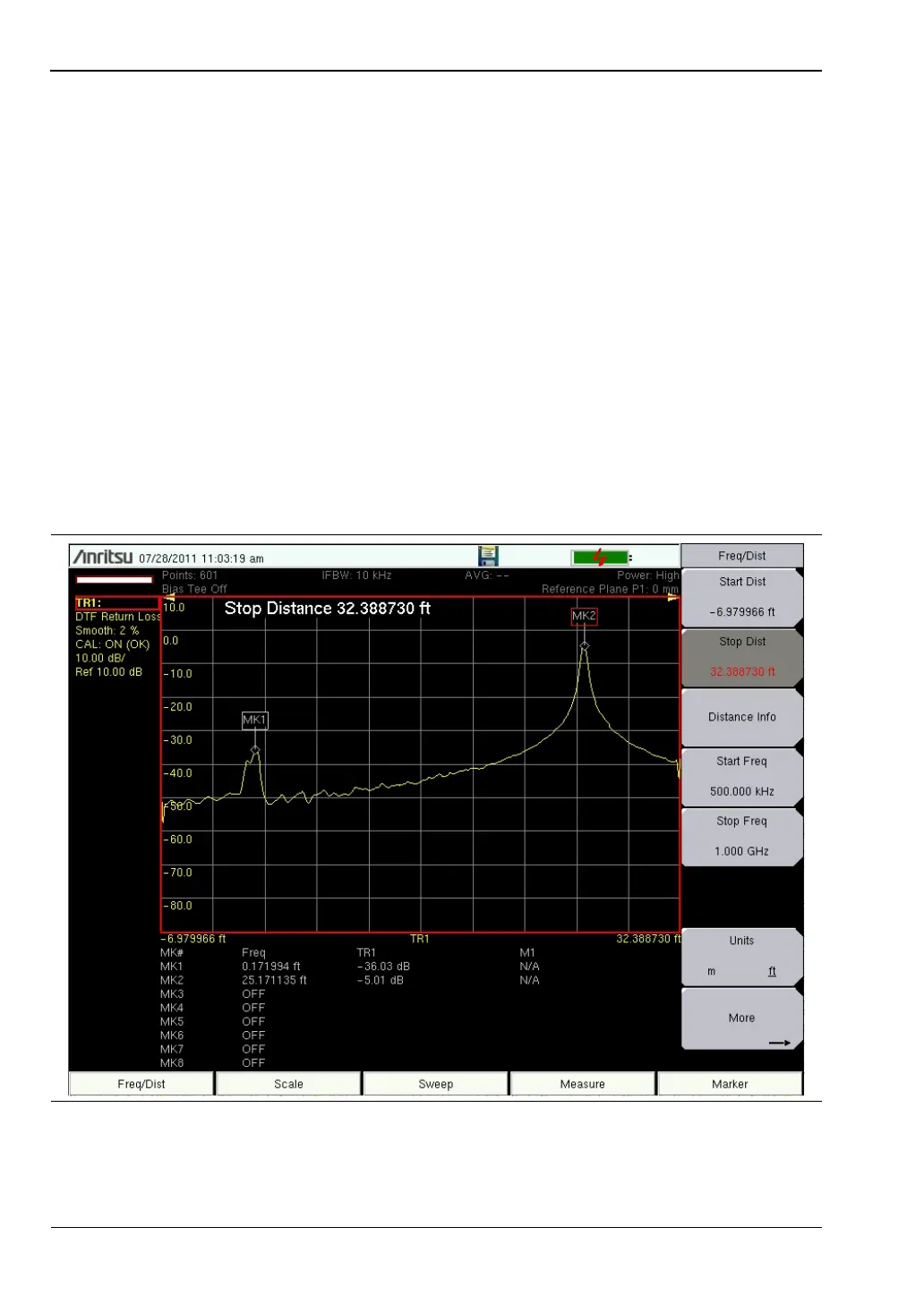
The example in this figure may not match the display on your instrument.
Figure 5-8. DTF Measurement With a 20 dB Attenuator at MK1 and an Antenna at Cable End