44
Note: When Both the Phone1 and Phone2 LTE measurement software are active, Receiver Diversity can be
selected at the Phone1 side only.
2.2.1.2.3. Connection using Aux Connector
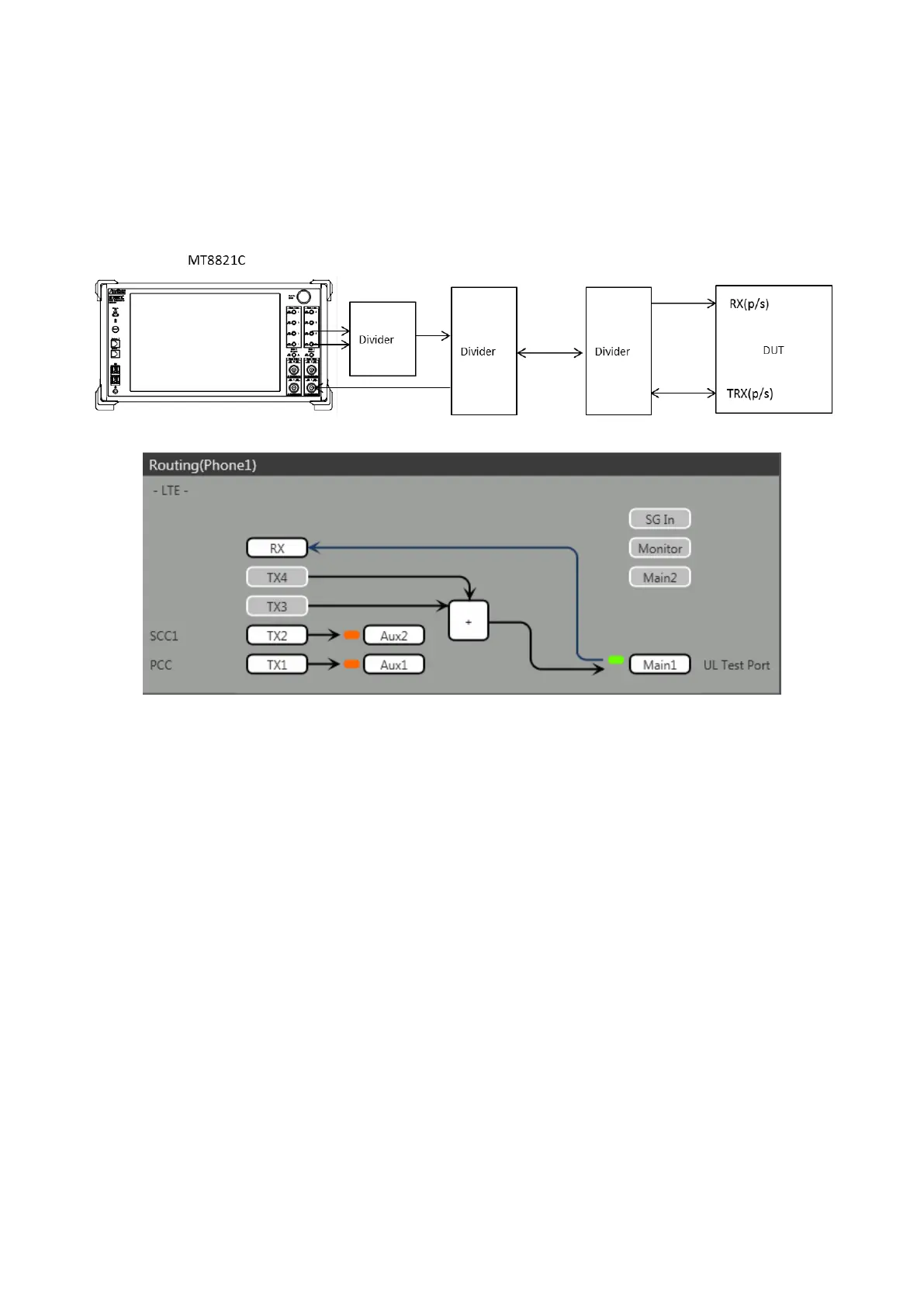
This example shows the connection diagram for the 2DL/1UL CA condition using Aux connectors. The DL signal of
PCC is output at the Aux1 connector and that of SCC-1 is output at the Aux2 connector, respectively
<Connection Diagram>
<Internal Routing Diagram>
Figure 2.2.1-5 Connection Diagram and Internal Routing Diagram for 2DL CA and 1UL CA, Tx and Rx Test
(MT8821C, using Aux connectors)
[Routing setting procedure]
1. Execute TXOUT 1, AUX to set the output connector System Config – Routing(Phone1) - Tx1 to Aux1.
2. Execute TXOUT 2, AUX to set the output connector System Config – Routing(Phone1) - Tx2 to Aux2.