45
2.2.1.3. Connection Diagram for MT8821C 2DL/2UL CA
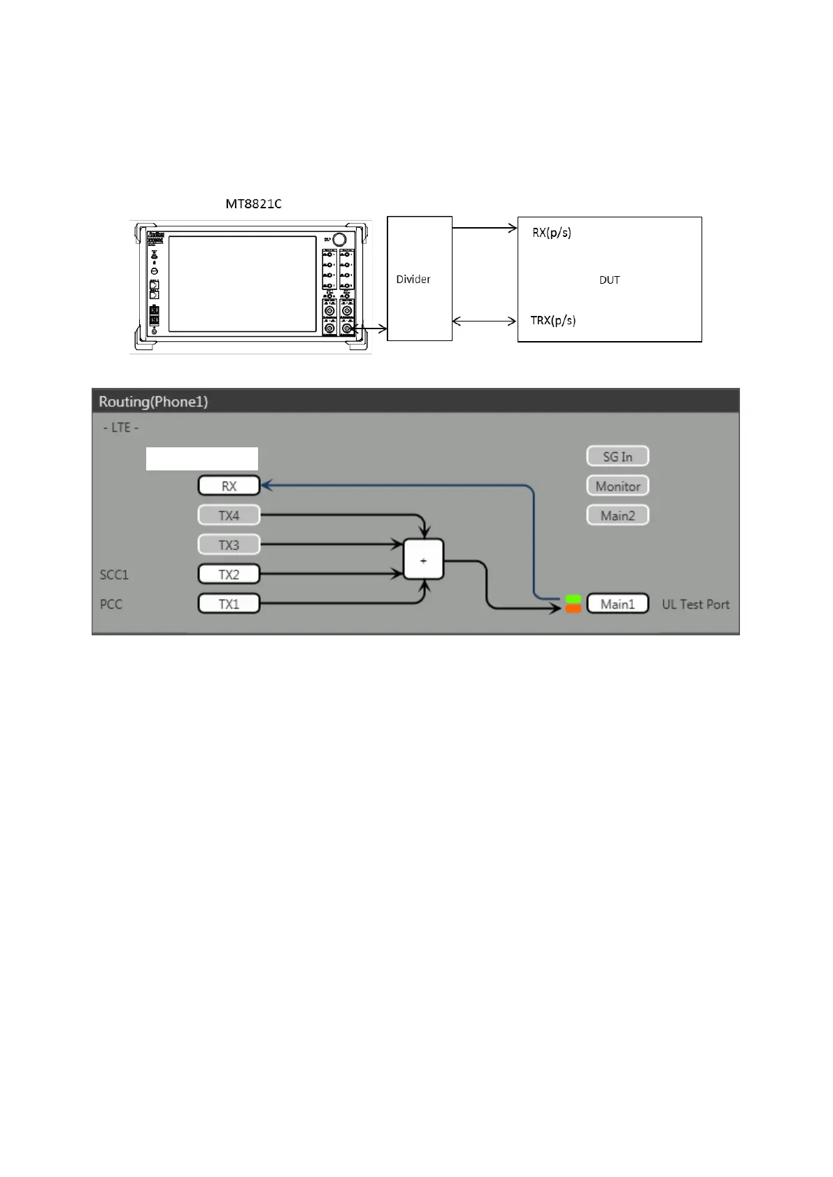
2.2.1.3.1. Connection using Main Connector
This example shows the connection diagram for the 2DL/1UL CA condition. The DL signals of PCC and SCC1 are
combined by the internal combiners of the MT8821C and output at the Main1 connector of Phone1.
The MT8821C can measure the Tx signals of both of PCC and SCC1 at the Main1 connector of Phone1.
<Connection Diagram>
<Internal Routing Diagram>
Figure 2.2.1-6 Connection Diagram and Internal Routing Diagram for 2DL CA and 2UL CA, Tx and Rx Test
(MT8821C, using divider)
[Routing setting procedure]
1. Execute TXOUT 1, MAIN to set the output connector System Config – Routing(Phone1) - Tx1 to Main.
2. Execute TXOUT 2, MAIN to set the output connector System Config – Routing(Phone1) - Tx2 to Main.