208 Installation
PRESS RIGHT KEY FOR
ENTRY MENU LE VEL 1
International ground symbol
(black on green background)
identifies main equipment
r
n
nn
i
n
n h
ink
Control
terminals
5 po w er
terminals
EL1/2/3
F- F +
Air flow
direction
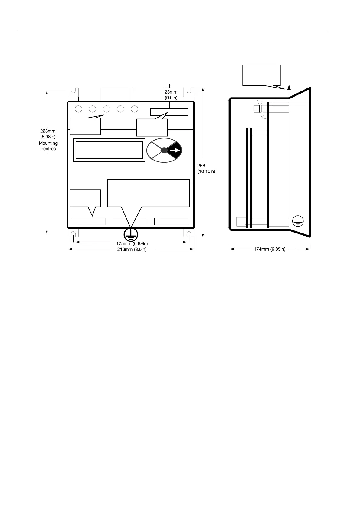
14.5 Mechanical dimensions PL/X 5 - 50
Unit w eight 5Kg
Symbolic drawing sho wn with end caps removed
14.5.1.1 Mounting PL/X 5 - 50
Four corner slots are provided to mount the unit. Use M6 (1/4 in) scre ws.
All mounting hole di mensions are + /- 2 mm.
A substantial earth connection should be made to the busbar provided.
Nominal cooling air throughput is specified in the rating table. (Use cool, clean, dry, filtered air).
Do not block the heatsink fins. Allow at least 50mm (2 in) space above and belo w the unit.
Ensure connections to power terminals are tight. Po w er terminal fastenings are M6.
See 14.10 Terminal tightening torques.
The units must be orientated vertically as sho wn.
The dimensions on this dra wing are for the footprint.
Overall dimensions are Width 216 Height 289 Depth 174
Unit weight 5Kg