16 User Manual Synertia® RF Generator
The information contained in this manual is subject to change by Comet Yxlon without prior notice.
• Optional User Port / Fieldbus Interlock (see chapter 9 “Interface specifications” on
page 75)
If present, two specific pins of this connector have to be connected to each other
externally to enable RF power operation.
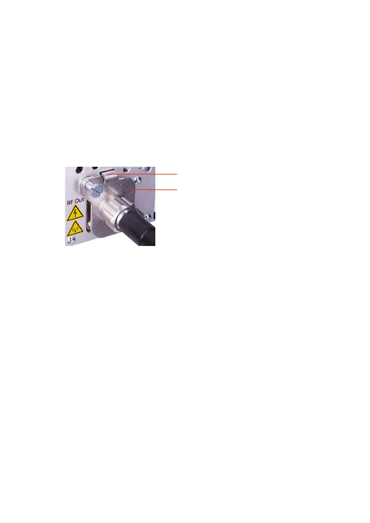
• RF Output Connector Check Switch
As shown in Figure 4 and in the interlock circuit diagram (Figure 3), the proper
connection of a coaxial cable to the RF output of the generator closes the
generator interlock chain via the switch plate and the corresponding RF Output
connector check switch inside the generator.
This finger closes the switch of the RF Output
connector inside the housing.
Spring loaded switch plate in position when the nut of
the RF coaxial cable is securely tightened.
Figure 4: RF Output connector with switch plate on the back of air-cooled generator
If one element of the interlock chain remains open, the RF power operation is disabled by:
• interrupting the DC supply voltage of the Pre-Driver via a DPDT relay
• disabling the AC/DC converter circuit which is used for the DC supply of the Pre-
Driver
• disabling the gate bias supply of the RF Driver by connecting the gate bias voltage
node to ground
• disabling the DC output of the AC/DC Power Converter supplying the RF Driver
and the RF Power Amplifier