User Manual Synertia® RF Generator 85
The information contained in this manual is subject to change by Comet Yxlon without prior notice.
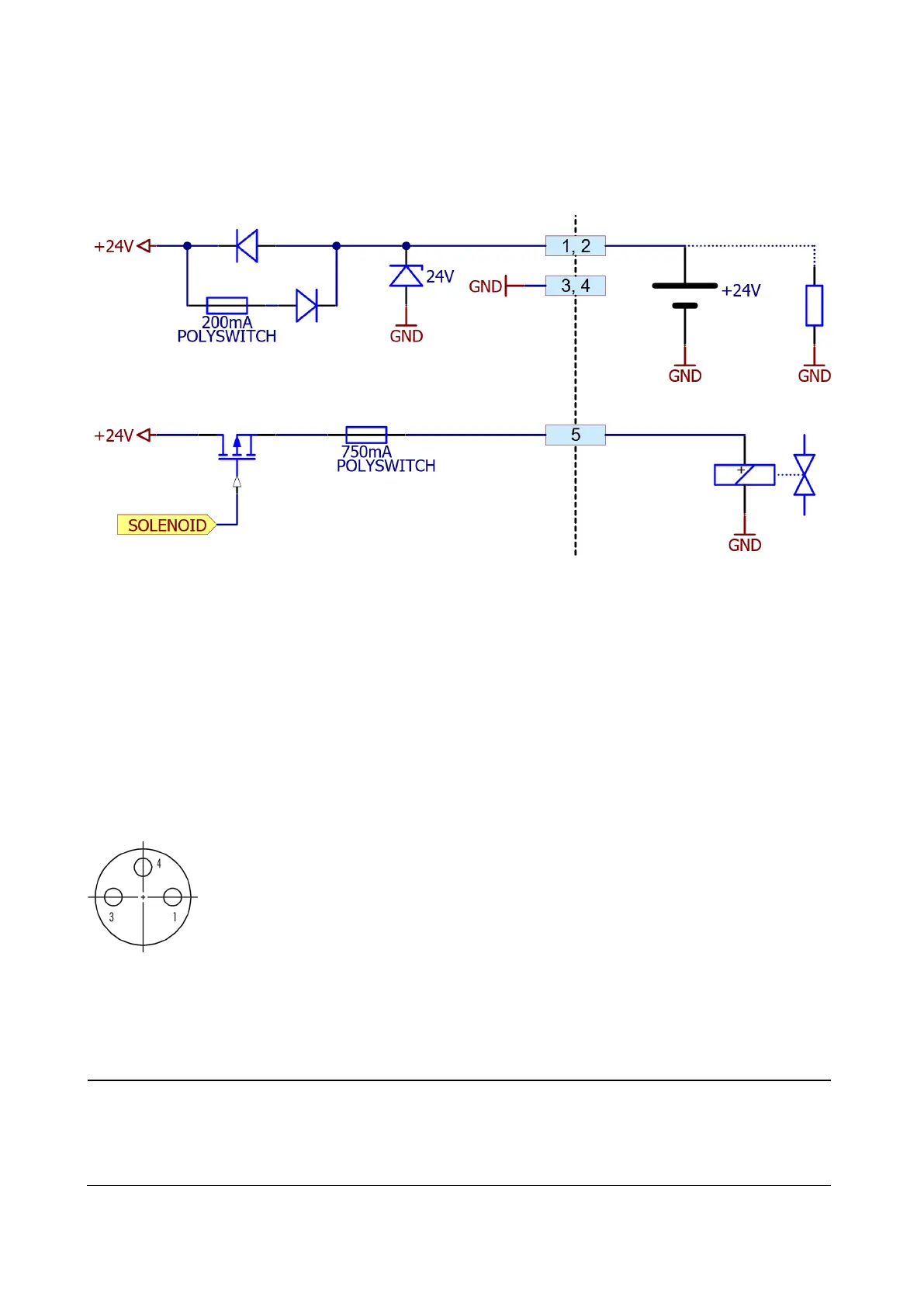
9.4.2 Schematics for 5-pin DC-Supply
Table 23: DC-Supply
9.5 Interlock interface
9.5.1 Signals on the 3-pin M8 Interlock connector
The following table shows the configuration of the 3-pin M8 Interlock connector.
Figure 52: Interlock connector
V provided at this output is the supply
the external interlock chain.
The output is protected by a self
-resetting
mA fuse.