28 User Manual Synertia® RF Generator
The information contained in this manual is subject to change by Comet Yxlon without prior notice.
Interfaces
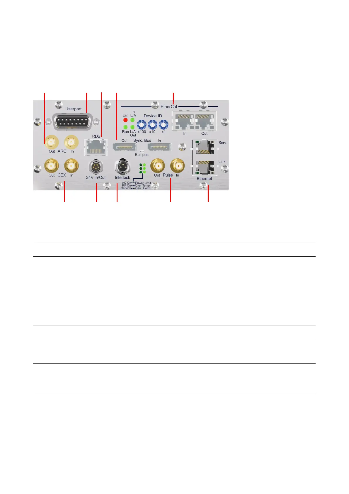
Please note, that the interface configuration shown below is just an example.
6 7 8 9 10
Figure 11: Interfaces on the back of air- and water-cooled Synertia® RF generators
Mainboard
1 CEX Out/In For connecting and synchronizing the RF output
signal of the Synertia® RF generator to other
generators on-site (initiator or receiver operation);
for additional information, see section 9.3 “
CEX
SMA
coaxial,
female
Standard
DC-Supply
For connecting an external auxiliary supply voltage
(24 V) for the internal controller, e. g. to hold up the
communication via any interface although AC mains
is switched off
male
3 Interlock For connecting a superordinate system interlock
M8 3-pin,
Standard
4 Pulse Out/In For connecting and synchronizing the pulsed
operation of the Synertia® RF generator to other
generators on-site (initiator or receiver operation)
SMA
coaxial,
female
Standard
5 Ethernet/Serv Ethernet interface for connecting the
Synertia® RF generator to other devices in an
existing TCP/IP network for manual
RJ45 Standard
Ethernet/Link Ethernet interface for connecting the
Synertia® RF generator to other Comet devices in an
existing TCP/IP network with the intent of remote
control by the customer’s system control
RJ45
Table 11: Interfaces on the backs of air- and water-cooled generators – Mainboard