User Manual Synertia® RF Generator 27
The information contained in this manual is subject to change by Comet Yxlon without prior notice.
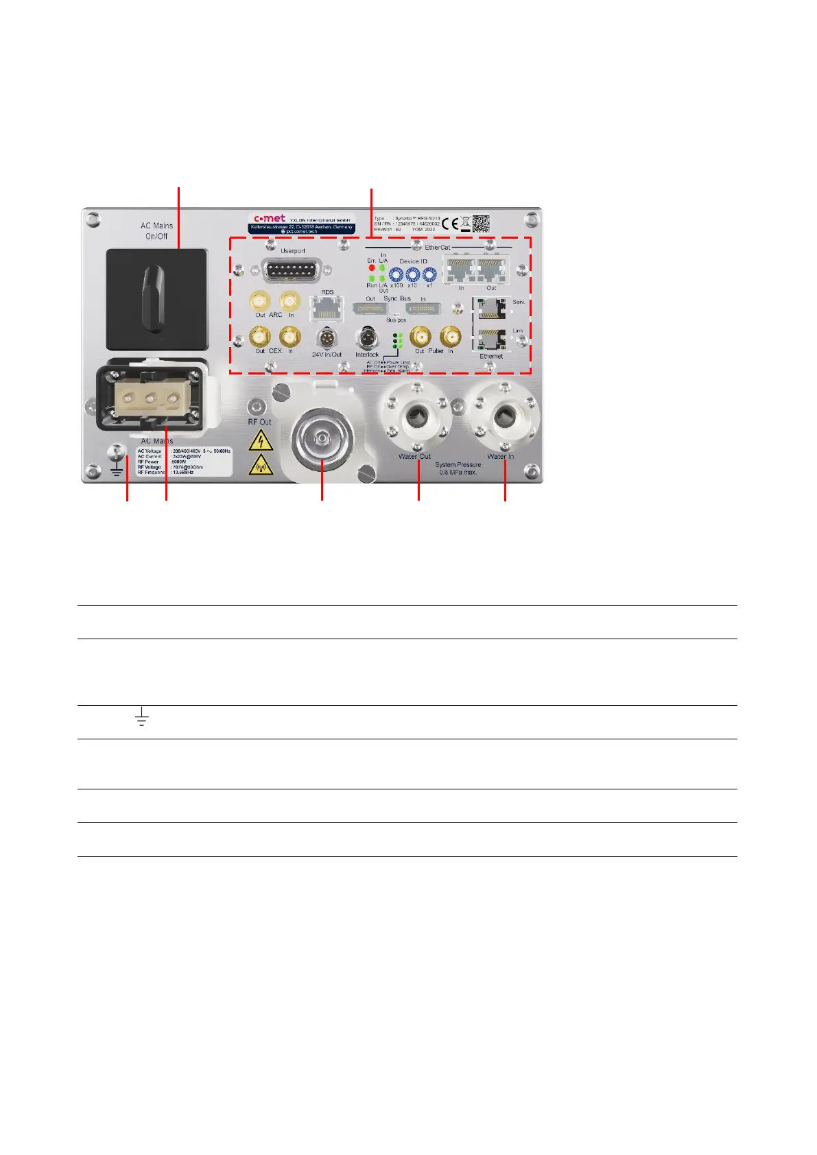
Back panel of the water-cooled generator
1
2
3 4 5
6 7
Figure 10: Back panel of water-cooled Synertia® RF generator
1 AC Mains On/Off LOTO capable switch for switching the mains voltage on
and off that allows the installation of a padlock for lockout
-
Interfaces: depending on device configuration. For details,
see Figure 11: Interfaces on the back of air- and water-
cooled Synertia® RF generators” and
Table 13: Interfaces
on the backs of air- and water-cooled generators“
3
Ground connector for equipotential bonding with the
system ground in an on-site installation
-
4 AC Mains Mains connector for connecting the 3-phase mains voltage
cable
Harting™ Han
Modular
5 RF Out Output for connecting the RF output line
Note: May differ from image depending on configuration!
7-16 type
Outlet for connecting the cooling water drain.
7 Water In Inlet for connecting the cooling water drain.
Note: May differ from image depending on configuration!
NPT 3/8 screw-
Table 10: Components on the back panel of the water-cooled generator