84 User Manual Synertia® RF Generator
The information contained in this manual is subject to change by Comet Yxlon without prior notice.
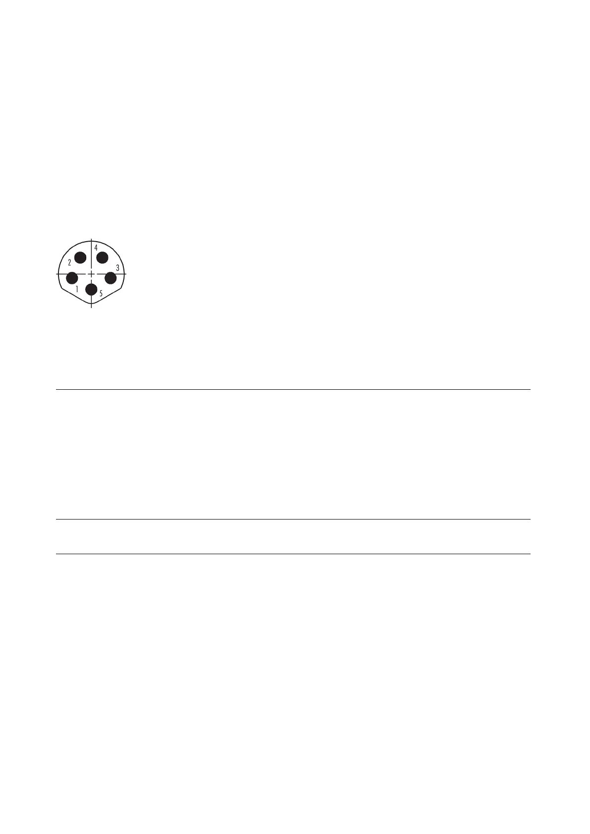
9.4 DC-Supply interface
9.4.1 Signals on the 5-pin M8 DC-Supply connector
The following table shows the configuration of the B-coded 5-pin M8 DC-Supply
connector.
Figure 51: DC-Supply connector
The control unit of the generator can be supplied
via these pins by applying 24
V with a current
A.
Via this supply input, the control unit can stay
alive even if the mains voltage drops for a longer
time
.
The second function of these pins is to provide a
supply voltage of 24
V for external use. This
self-resetting 200 mA
ground reference for the supply
V for connecting a
-cooled generators. It is
-resetting 750 mA fuse.
The solenoid is switched off when the generator is
not dissipating heat to prevent condensation
inside the generator.
Table 22: 5-pin M8 DC-Supply – Configuration