EasyManua.ls Logo

Comet Synertia RF - Schematics for 3-Pin Interlock; Figure 53: Interlock; Table 24: 3-Pin M8 Interlock - Configuration

Comet Synertia RF
125 pages
Print Icon
To Next Page IconTo Next Page
To Previous Page IconTo Previous Page
Loading...
86 User Manual Synertia® RF Generator
The information contained in this manual is subject to change by Comet Yxlon without prior notice.
Signal
Pin
Related
Pin
Signal
Name
Signal
Type
Description
2
Not populated
3
1
Interlock In
DI
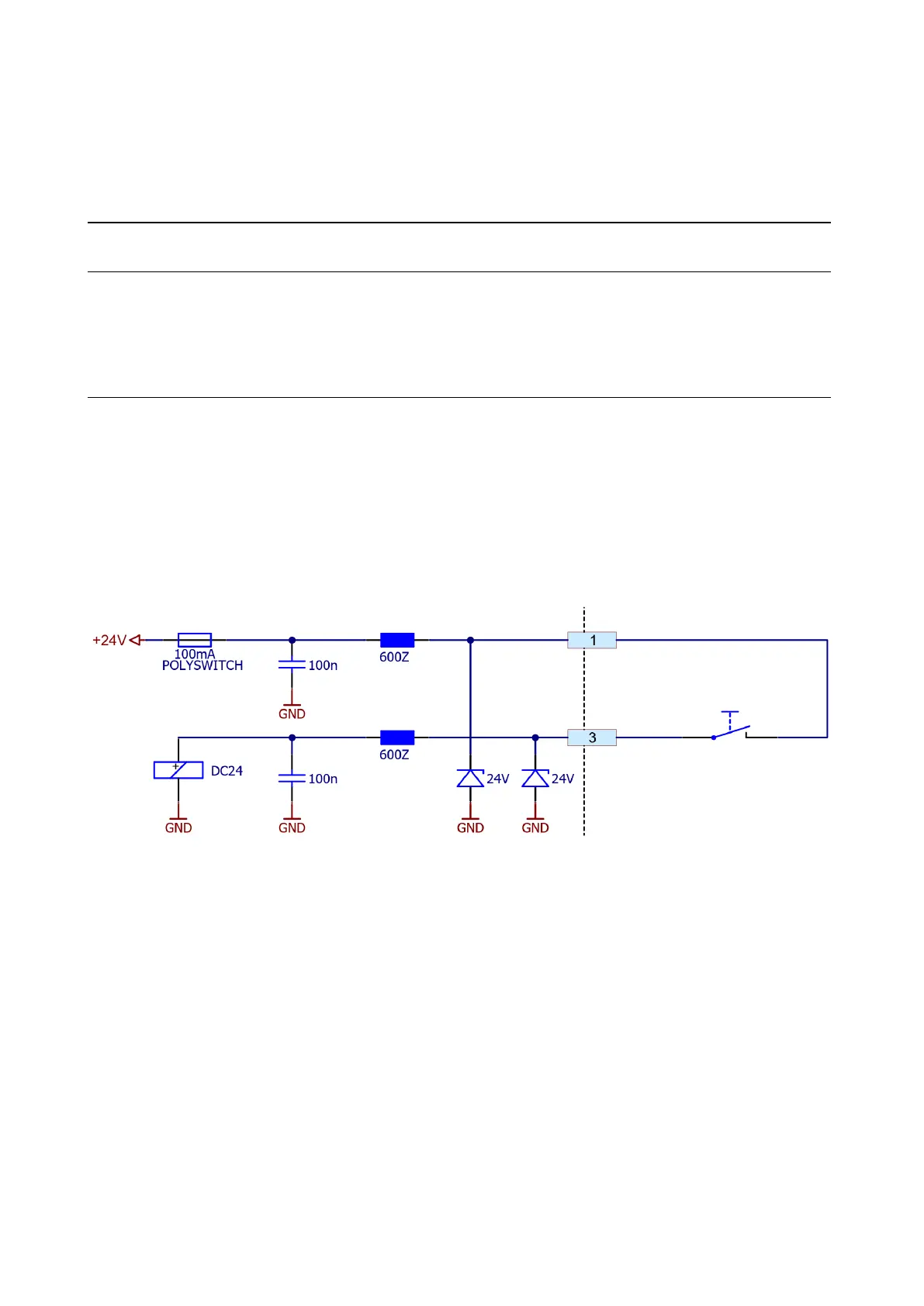
This is the input for closing the external interlock
chain.
The voltage of pin 1 or an external voltage of
20
24 V referenced to GND has to be provided
at this pin.
4
Not connected
Table 24: 3-pin M8 Interlock Configuration
9.5.2 Schematics for 3-pin Interlock
Figure 53: Interlock

Table of Contents