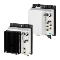
5 RAMO5 motor starter
5.4 Specific technical data
124 Rapid Link 5 · RAMO5 · RASP5 05/20 MN034004EN www.eaton.com
5.4 Specific technical data
The following tables show the technical data of the RAMO5 motor control
unit in the individual power classes along with the allocated motor output.
→
The motor output allocation is based on the rated operational
current.
→
The motor output indicates the respective active power output
to the drive shaft of a normal, four pole, internally or externally
ventilated three-phase asynchronous motor with 1500 rpm (at
50 Hz) and 1800 rpm (at 60 Hz).
Symbol Unit RAMO5-D… RAMO5-W…
Instance DOL starter
L1 → U, L2 → V, L3 → W
Reversing starter
FWD: L1 → U, L2 → V, L3 → W
REV: L1 → W, L2 → V, L3 → U
Block diagram
→ Page 125 → Page 126
Rated current (I
e
)I
e
A 6.6
Adjustable motor protection A 0.3 - 6.6
Assigned motor power at
400 V, 50 Hz
440 - 460 V, 60 Hz
PkW0.18 - 3
PHP0.25 - 4
Power supply side (primary side)
Number of phases 3
Rated voltage U
LN
V 380 V - 10 % - 480 V + 10 %, 45 - 66 Hz
Input current I
LN
A 0.3 - 6.6
Braking
Control voltage
(External brake)
UVRAMO5-xxx1…: 180 V DC
RAMO5-xxx2…: 230/277 V AC
RAMO5-xxx4…: 400/480 V AC
Load current (external brake) I A
0.6A, max. 6A for 120ms
Heat dissipation at
Rated current (I
e
)
P
v
W Max. 8 W, depending on motor current and brake
Weight (without/with repair switch) m kg
1.6/1.8
Response time
Motor On (automatic)
1)
t
ON
ms Motor 20-35, brake 20-35
Motor Off (automatic)
1)
t
OFF
ms Motor 20-35, brake 20-35
Switch off the motor (quick stop) t
Off
ms Motor 20-35, brake 20-35
Switch on Q1 t
ON
ms 2 - 20
Switch off Q1 t
OFF
ms 2 - 20
Minimum pulse duration I1/I2 t
ON
ms 5
1) without bus runtime, depending on PLC
 Loading...
