9 Communication
9.1 A S - In ter fa ce
196 Rapid Link 5 · RAMO5 · RASP5 05/20 MN034004EN www.eaton.com
9.1.7 Replacing Rapid Link devices in the ASi circuit
If a slave fails due to a fault, it can be replaced with an identical device with
an address of 0. The gateway will detect the replacement and will automati-
cally reassign the faulty slave’s address to the new slave. It may be neces-
sary to configure this feature on the gateway.
If the replacement device does not have a default address of 0, it will be
necessary to program it with the faulty device’s address.
9.1.8 ASi ribbon cable
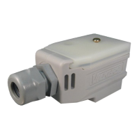
You can position M12 branches (ZB2-100-AZ1) at any point along the
ASi ribbon cable.
Both the mechanical and electrical connections are carried out in one
operation:
Release the black union nut until the contact tips no longer protrude.
Insert the two-wire profile ribbon cable and clip the junction shut.
Retighten the black union nut.
The device or module is now ready for operation.
Figure 105: Junction M12 (order no.: ZB2-100-AZ1)
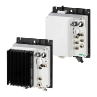
The Rapid Link 5 function modules have an ASi M12 plug-in connector that
fits the M12 junction.
→
You can use the AS-i gateway to delete the existing Rapid Link 5
device address and assign a new address.
→
For detailed information on addressing and troubleshooting
the
gateway, refer
to the manufacturer's manual.
Pin Function
1 AS-Interface+
2
0 V
3 AS-Interface -
4 +24 V DC
5 –
 Loading...


