5 RAMO5 motor starter
5.1 Designation
Rapid Link 5 · RAMO5 · RASP5 05/20 MN034004EN www.eaton.com 121
5 RAMO5 motor starter
5.1 Designation
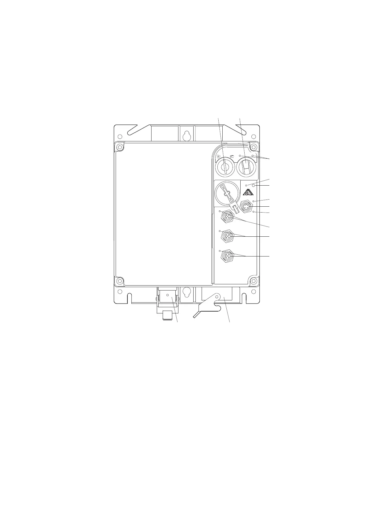
Figure 75: Overview of RAMO5
a Key-switch for manual and automatic mode and Reset
b Selector switch for rotating field direction (FWD, REV) in Manual mode, only for RAMO5-W...
c LED for indicating motor voltage rotating field
– FWD = Clockwise rotating field (Forward Run)
– REV = Counterclockwise rotating field (Reverse Run)
d LED display for supply voltage
e LED display for fault or error messages
f LED display for AS-Interface
g Connection AS-Interface (M12 connector)
h LED display for AS-Interface communication error
i Sensor input I1 (M12 socket) with LED
j Actuator output Q1 (M12 connector) with LED display - only in the version RAMO5-xx1…
k Sensor input I2 (M12 socket) with LED
l Motor feeder plug
m Power plug, (supply voltage 3 AC 400 V, N, PE)
REV FWDOFF
PWR FLT
SEN I1
I1
ACT Q1
Q1
SEN I2
I2
AS-I
Data
Fault
OFF/RESET
①
②
⑪
⑬
⑨
⑩
⑧
④
⑥
⑤
⑦
⑫
③

 Loading...


