2 Engineering
2.9 Sensor inputs
Rapid Link 5 · RAMO5 · RASP5 05/20 MN034004EN www.eaton.com 61
2.9 Sensor inputs
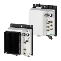
Figure 23: Connection sockets of sensor inputs
The RAMO5 and RASP5 Rapid Link 5 modules have two M12 sockets for
direct connection of sensors.
Figure 24: Pin assignment for RASP5
Pin Configuration
1 +24 V DC (160 mA) – output
2
Sensor input
3
0 V (reference potential)
4
Sensor input
5
Not used
SEN I1/I3
PWR FLT
I1
SEN I2/I4
I2
I3
I4
STO
FAN
AS-I
Data
Fault
1
3
2
4
5
1
3
2
4
5
 Loading...
