2 Engineering
2.3 Repair switches
Rapid Link 5 · RAMO5 · RASP5 05/20 MN034004EN www.eaton.com 41
2.3 Repair switches
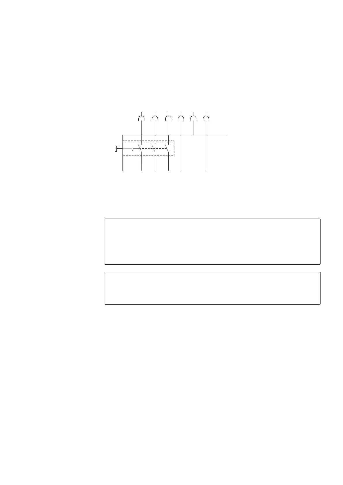
The device versions RAMO5-…-…RS1 and RASP5-…-…R…S1 are equipped
with arepair switch that disconnects the Rapid Link 5 modules from the
mains voltage in all three phases
.
Figure 13: Repair switch in position 0 = OFF
→
Before operating the repair switch, the motor must have stop-
ped.
DANGER
Before performing maintenance or repair work on RASP5 units,
make sure to wait until the DC-Link voltage discharging time
(at least five minutes) has passed.
This also applies when handling the motor.
ATTENTION
For RASP5 units, the pause between two power-on operations
must be at least one minute.

 Loading...


