3 Installation
3.4 Power bus
Rapid Link 5 · RAMO5 · RASP5 05/20 MN034004EN www.eaton.com 93
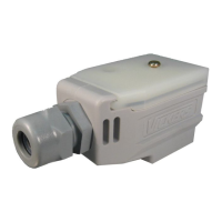
3.4.1.3 Installing the end piece
First slide the lower (shorter) part of the RA-C1-END1 ribbon cable end
piece onto the prepared flexible busbar.
Slot the individual conductors into the insulation channels in the ribbon
cable end piece as far as they will go.
Join the upper and lower sections using the two clamping screws.
Installed correctly, the flexible busbar offers degree of protection IP65.
Figure 52: RA-C1-END1 ribbon cable end piece
3.4.1.4 Flexible busbar junction connections
The supply and outgoer modules can be installed at any point along the flexi-
ble busbar without interrupting the busbar’s conductors. The connection is
made with contact screws.
Figure 53: Pin assignment of the
Flexible busbar junction
RA-C1-PLF1
Pin Function Wire number
(7 x 4 mm
2
)
1 L1 1
2 L2 2
3 L3 3
4 N 4
5 +24 V
1)
5
6 0 V
1)
6
PE PE yellow/green
1) Not used on RAMO5 and RASP5.
L2 L3
NL1PE
 Loading...
