11.1.2 2 Ball-Valves
11.1.3 Inserting the metering valves in the correct positions
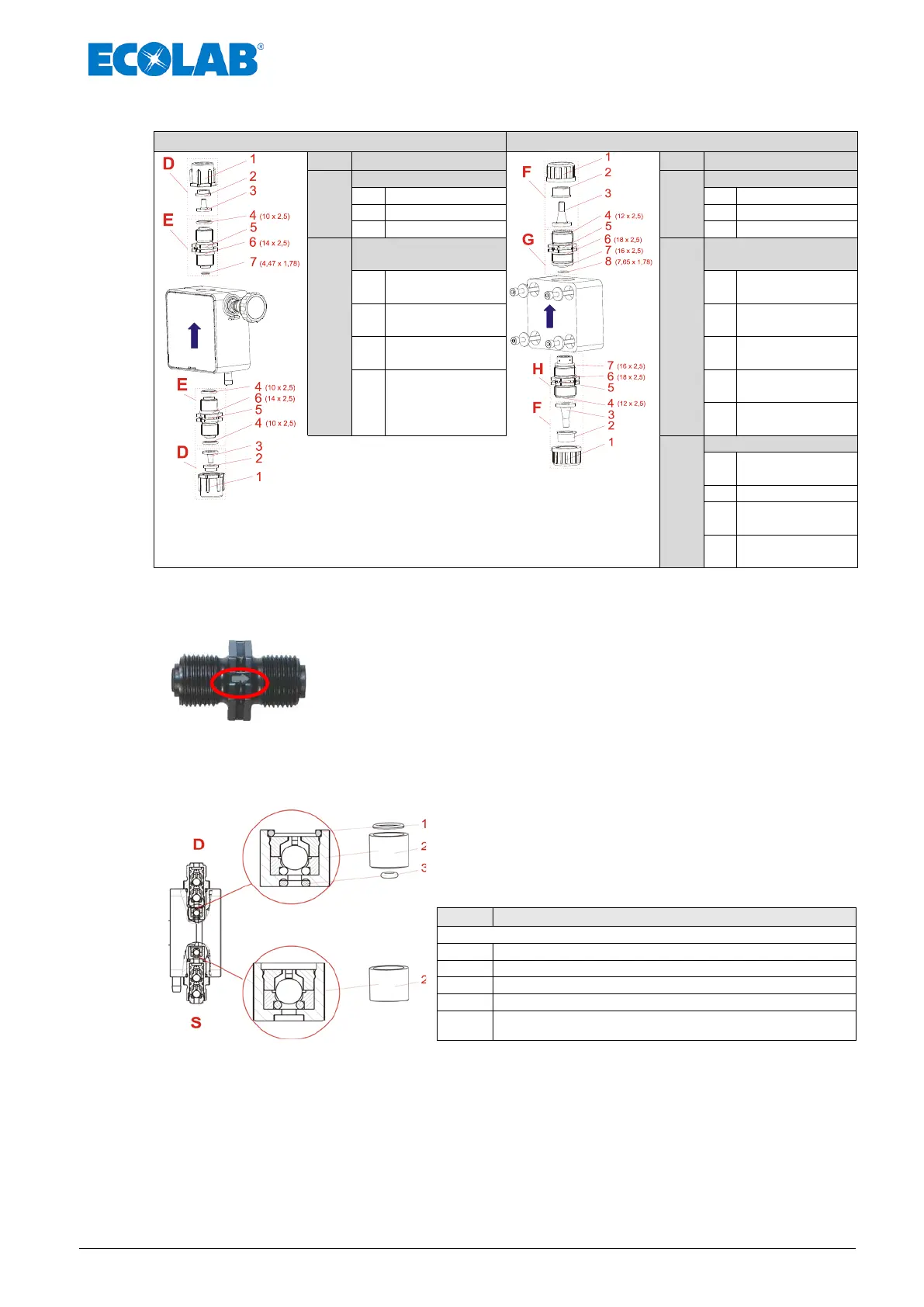
On the suction valves and pressure valves, the flow direction is
marked with an engraved arrow.
When inserting it, always ensure that the valves are inserted
according to the flow direction!
Fig. 11.4 Inserting the metering valves in the correct positions
11.1.4 Changing the valve cartridges, type V3
Fig. 11.5 Changing the valve cartridges, type V3
When replacing the V3 valve cartridges, ensure that
they are inserted in the correct position.
The small O-ring (Pos. 3) must be inserted so that it
points downwards (in the direction of the pump head)
Upper valve cartridge consists of:
Pressure side -> Pressure valve
Suction side -> Suction valve
The lower valve cartridge is inserted without O-rings. However, its location corresponds to the
upper valve cartridge. Therefore, the groove must point in the direction of the pump head in
which the large O-ring (Pos. 2) would fit.
1,4 – 11,2 l/h for type: 00014 - 00112
Fig. 11.2 Maintenance:
2 Ball Valve, 24l/h for
type: 00240
D
F
E
G
7
O-Ring,
Ø 4,47 x 1,78
7
8
Fig. 11.3 Maintenance:
2 Ball Valve (V3), 1,4 – 11,2l/h
for type: 0014 – 00112
H
7

 Loading...


