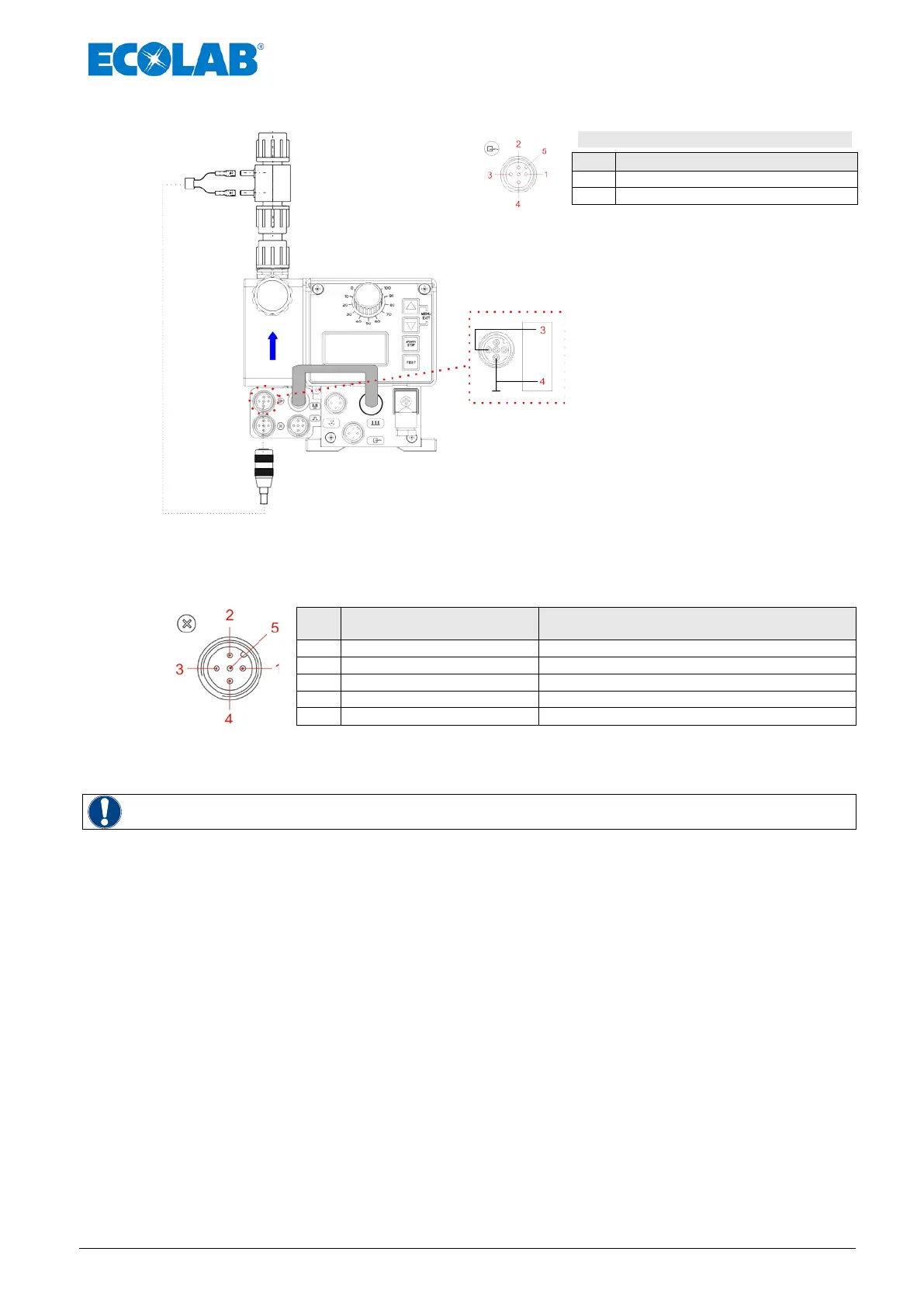
8.2.2.1 Installation MicroFlow Transducer
3 + 4 = MicroFlow- Transducer
Signal input MicroFlow- Transducer
Fig. 8.7 Installation MicoFlow- Transducer
8.2.3 Connector assignments of Slot VII (5-terminal)
Input for batch pulse and metering lock
Pin
Conductor coloring
(cable connection)
Assignment
Output 5 V, DC (load with max. 50 mA)
Fig. 8.8 Connector assignments of Slot VII (5-terminal), input for batch pulse and metering lock
Remove the protective cap
Mount the connector plug according to the connector assignment.
WARNING
Only use a connector plug from our product range!

 Loading...


