7.1.2 Connecting the suction pipe and pressure pipe
Pressure-side O-ring (metering)
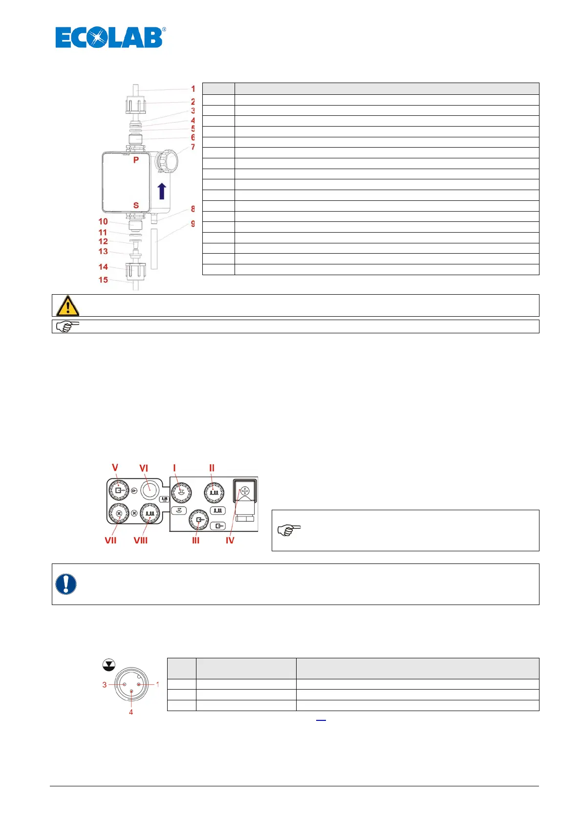
Fig. 7.8 Connecting the suction pipe and pressure pipe
CAUTION
When connecting the suction and pressure pipes, ensure that the O-rings (Pos. 5 and 11)
are fixed to the connectors so as to achieve the required seal.
The use of an appropriate suction pipe from our product range is recommended.
Trim the tube to the precise length
Slide the union nut (Pos. 2 and 14) and clamping piece (Pos. 3 and 13) over the tube and
attach the tube to the taper up to the stop collar (Pos. 4 and 12).
Insert the O-ring (Pos. 5 and 11) into the valve groove and tighten the union nut.
Place the suction pipe in the delivery bundle.
7.2 Electrical installation
7.2.1 Inputs and outputs
Fig. 7.9 Electrical installation: Inputs and outputs
The inputs and outputs in are equipped with protective
caps in the as-delivered condition. These caps must be
removed when necessary. (Pos. I-VIII)
NOTE
Since the protective caps or connector
plugs are coded, the respective images
must be observed (I-III). Do not use force
WARNING
To protect the electronics against contact with chemicals or humidity, never operate the
metering pump without protective caps or connector cables, since the connectors can
become oxidized. Mixing up the protective caps may result in malfunctions of the pump
and/or damage to the connectors!
7.2.2 Connector assignments of Slot I (3-terminal)
input for low-level advance warning and empty report
Pin
Conductor coloring
(cable connection)
Assignment
(plug assignments: see also chapter 14 “Technical Specifications“)
Fig. 7.10 Connector assignments of Slot I (3-terminal), input for low-level advance warning and empty report
 Loading...


