7 Device installation
7.1 Hydraulic installation
7.1.1 Installation examples
NOTE
The installation examples and applications provided here are of a functional nature. They
give an overview of installation types which are correct or to be avoided for the correct
WARNING
Specific measures and protection devices for the metering of dangerous or aggressive
chemicals are not provided here.
When using such chemicals, always observe the legal regulations and the relevant
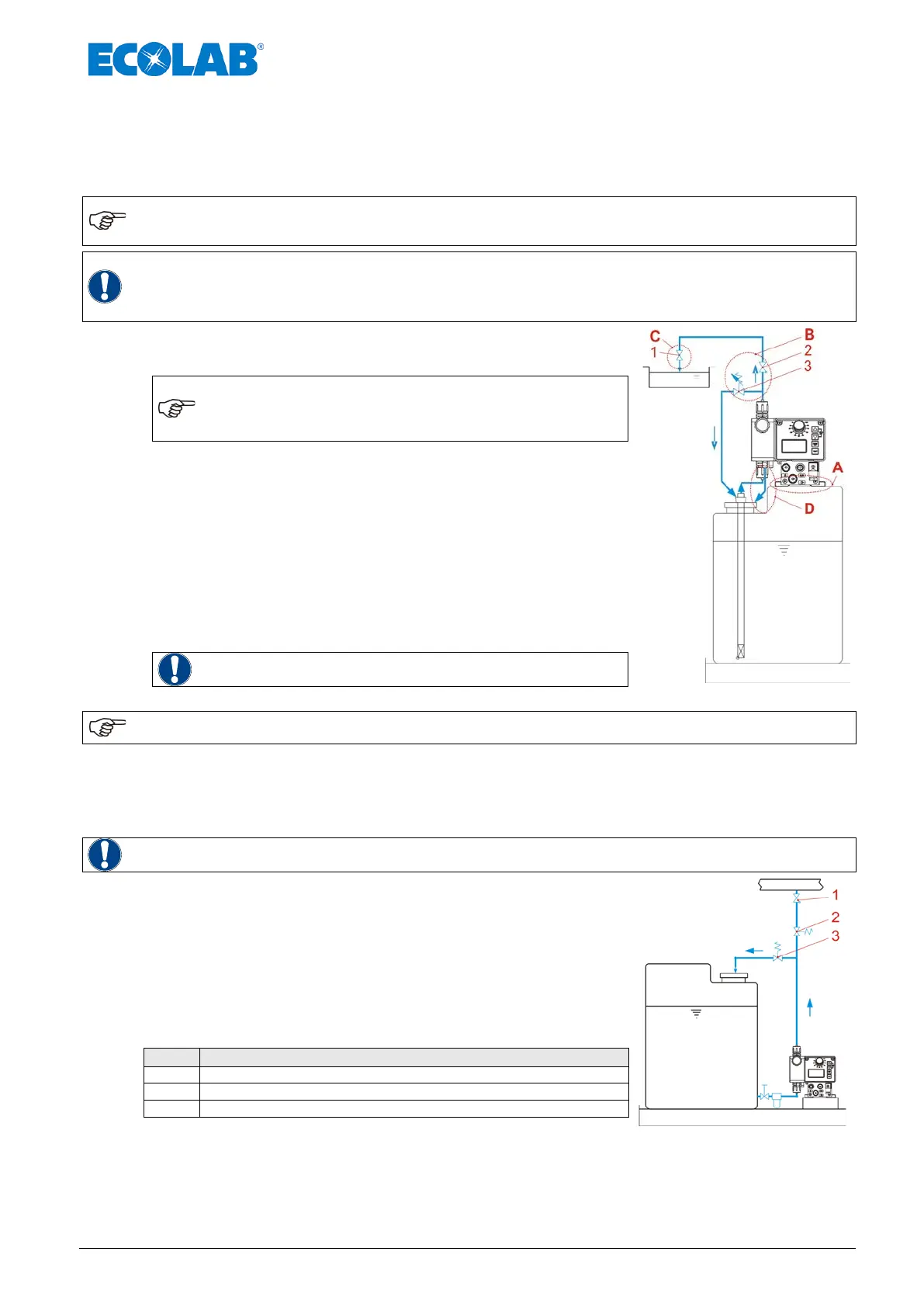
A) The arrangement of the metering pump should preferably
be made on and/or over the metering container.
NOTE
For media with a tendency towards sedimentation,
the bottom admission valve or foot valve of the
suction line / suction lance must be fitted above
the anticipated layer of sludge.
B) Between the back-pressure in the injection point and the
pressure at the metering pump a positive difference of
pressure must prevail of at least 0.1 MPa (1 bar). If this is
not the case, a pressure control valve (Pos. 2) must be built
into the metering line.
In addition it recommends to install itself for the avoidance
of inadmissibly high pressures in the metering line an
appropriate safety overflow valve (Pos. 3). The by-pass
pipe of this valve should be led back pressure-free into the
container.
WARNING
The overflow line never be fed back into the
suction line of the metering pump.
Fig. 7.1 Hydraulic installation:
NOTE
In place of a pressure valve and an overflow valve also a multifunction valve (MFV) from our
delivery program can be used.
C) A spring-loaded injection or metering valve (Pos. 1) should be installed at the injection
point (including with supplying metered amounts into depressurised systems).
D) For easy venting of the metering pump, the vent connection (see chapter 5, Fig. 5.1,
Pos. 3) should be fed back into the metering medium container via a separate pipe.
WARNING
The venting pipe must never be fed back into the suction side of the metering pump!
For outgassing media and products with a viscosity of > 100
mPas, flooded suction is recommended.
In using this method, however, ensure that the injection point
is positioned over the discharge container and/or an
appropriate pressure control valve (Pos 2) is installed.
These measures prevent the discharge container from being
siphoned empty.
Injector valve / Metering valve
Fig. 7.2 Hydraulic installation: installation examples 2
 Loading...


