7.2.2.1 Installing the suction pipe with low-level advance warning and empty report
NOTE
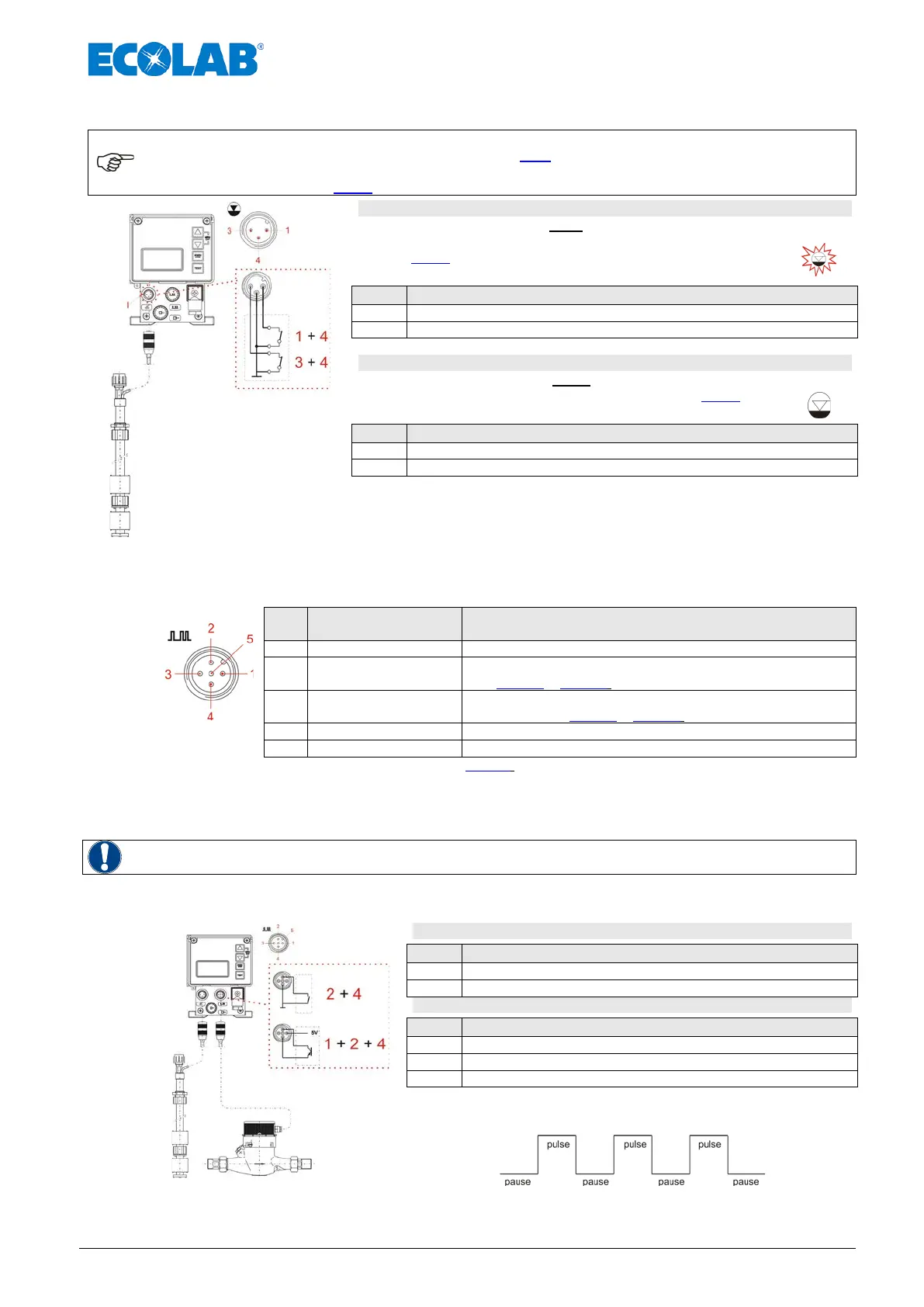
Slot I must always be assigned, either through the mounted strapping plug (protective cap
with corresponding symbol; see chapter 7.2.1, Fig. 7.10, Pos. I) or through connection to
the empty report device (suction lance plug). The setup of low level contact is invertible.
(see chapter 10.3.8 “Configuration Low level contact“)
1 + 4 = Input low-level warning
low-level advanced warning open:
low-level advanced warning active (invertible circuit logic, see
chapter 10.3.8), empty report symbol on display flashes, pump is
not locked.
3 + 4 = Input empty report
Switch contact empty report open:
empty report active (invertible circuit logic, see chapter 10.3.8),
empty report symbol on display appears, pump is locked.
Fig. 7.11 Installing suction pipe with low-level advance earning and empty report
7.2.3 Connector assignment of slot II (5-terminal)
input for pulse signal, standard signal, metering lock, batch and metering monitoring
Fig. 7.12 slot II
(5-terminal)
Pin
Conductor coloring
(cable connection)
Assignment
output 5 V, DC (loadable with max. 50 mA)
2
white
pulse input (also as configurable batch / metering monitoring;
see 10.3.13 & 10.3.15)
3
blue
metering lock (also as configurable batch / metering
monitoring, see 10.3.13 & 10.3.15)
Input standard signal 0/4...20 mA
(plug assignments: see also chapter 14.3.5.2 “Pin assignment / conductor coloring Connector II (5-
terminal)“)
Remove the protective cap
Mount the connector plug according to the connector assignment.
WARNING
Only use a connector plug from our product range! (included in the delivery scope)
7.2.3.1 Installing the pulse control (water meter)
Fig. 7.13 Installing the pulse control
2 + 4 = Pulse input with potential-free contact
1 + 2 + 4 = Pulse input with electronic switch (NPN)
The minimum pulse- or pause time is 15 ms.

 Loading...


