9.4 Key functions
MENU/EXIT function entry and exiting of the menu levels (keep keys pressed down together)
() Modify set values upwards
() Modify set values downwards
Stop the pump
Confirmation key (ENTER) for set values
Fig. 9.4 Start/Stop
Test function (endurance test)
9.5 Description of display symbols
Pump’s operation mode: the top right indicator in the display makes a full rotation with each
stroke.
Level report is active (flashing display = low level advance warning, display is permanently visible
= empty report), see 7.2.2.1 Installing the suction pipe with low-level advance warning and empty
report or 10.3.8 Configuration / Low-level contact
Metering lock active, see 7.2.3.3 Installing the control via the metering lock or 10.3.7
Configuration / Metering lock
Fault report, see 12.2 Alarm messages
Operation mode internal, see 10.2.2 Operation mode / internal
Operation mode pulse multiplication, see 10.2.3 Operation mode / pulse
Operation mode pulse division, see 10.2.3 Operation mode / pulse
Operation mode current x – xx mA, see 10.2.4 Operation mode / current
Operation mode batch see 10.3.15 Configuration / Batch
Display strokes / min at Operation mode internal
Display % at Operation mode internal
Display l/h at Operation mode internal see 10.2.2.2 Display / setting operation mode internal
Display at operation mode pulse, see 10.2.3.2 Display / setting operation mode pulse
Display at operation mode current, see 10.2.4.3 Display / operation mode current
Display of the current metering frequency in %
Pump is in operating state OFF (must be switched on)
Dongle box is connected, see 8 Upgrading to Version Chem-Ad
®
Serie B E60
Plus
E60++
Dongle box and OGM
PLUS
are connected, see 8.2.1.1 Installing the oval gear meter or 10.3.11
Configuration / Oval gear meter
Alarm operation mode, see 12.2 Alarm messages
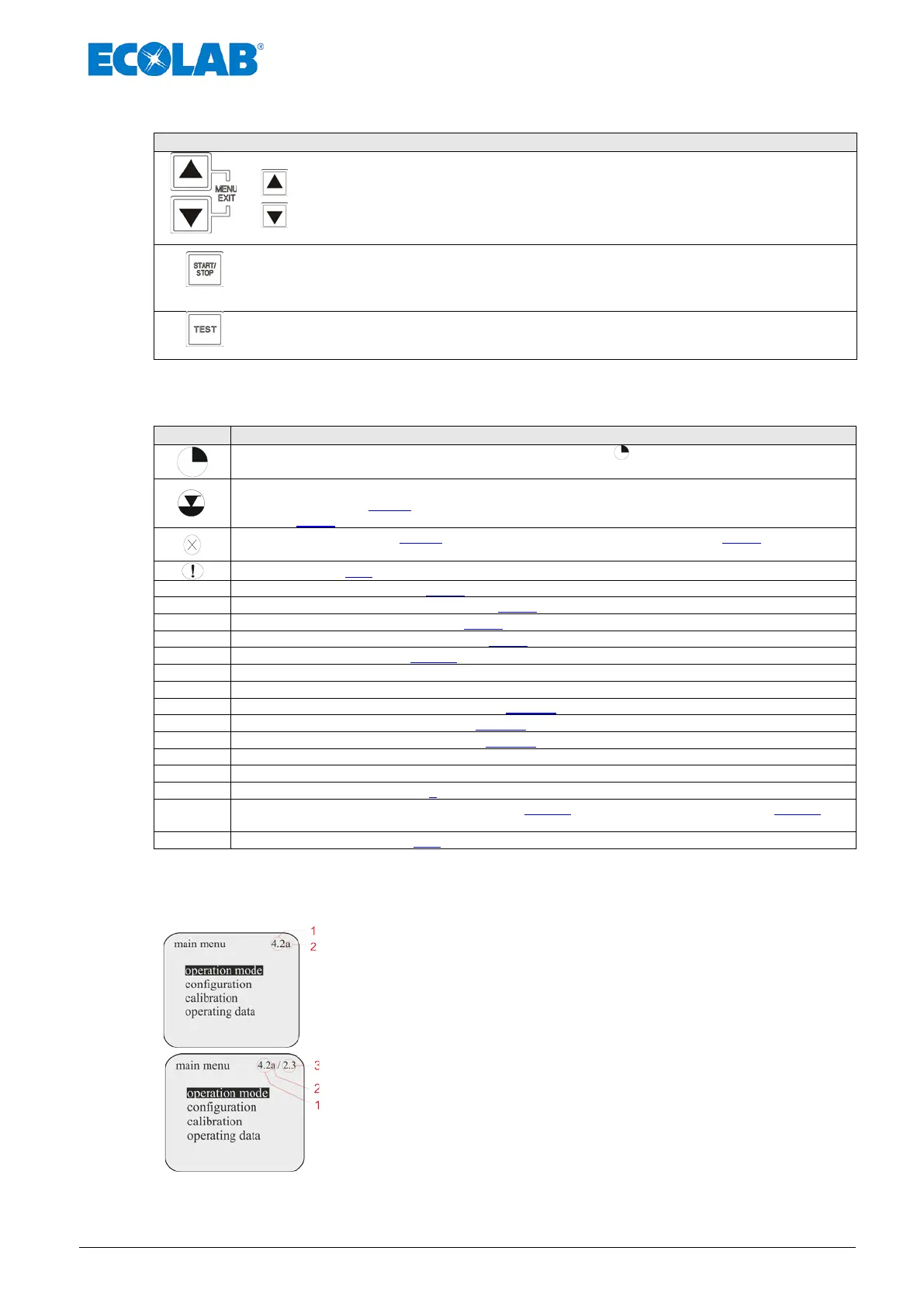
9.6 Software version display
The current software version (Pos. 1) is displayed (Fig 9.6 & 9.7) in
the top right of the main menu screen
Lowercase letters after the software number (Pos. 2) describe
internal software modifications that do not affect the operation of
the device.
Fig. 9.6 Software version display 1
If a Dongle box or a MicroFlow
PLUS
has been connected, the unit
version (Pos. 3) is displayed to the right of the pump version.
Fig. 9.7 Software version display 1

 Loading...


