ESR series service routers.ESR-Series. User manual
•
•
Table 34 – Description of connectors, LEDs and controls located on ESR-10 rear panel
№ Front
panel
element
Description
1 ON/OFF Power on/off button.
2 12V DC Connector for power adapter connection.
3 Console Console port RS-232 (RJ-45) for local management of the device.
4 USB1, USB2 2 USB connectors for connecting external USB devices.
5 [1.. 4] 4 ports of Gigabit Ethernet – 10/100/1000BASE-T (RJ-45).
6 Optical
Ports
2 ports of Gigabit Ethernet-100/1000BASE-X (SFP).
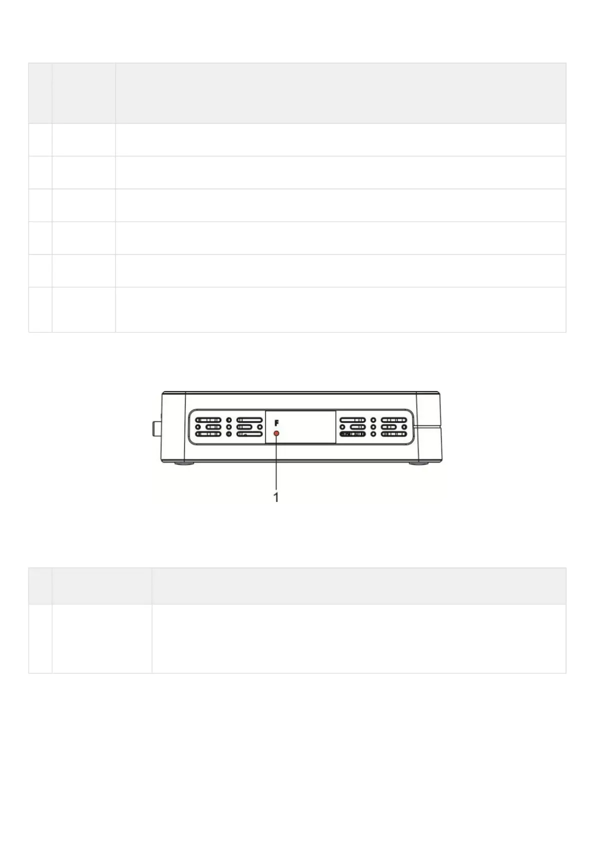
ESR-10 side panels
The side panel layout of ESR-10 is depicted in figure 48.
Figure 48 – ESR-10 side panel
Table 35 lists right panel controls of the router.
Table 35 – Right panel connectors description
№ Side panel element Description
1 F Functional key that reboots the device and resets it to factory default configuration:
pressing the key for less than 10 seconds reboots the device.
pressing the key for more than 10 seconds resets the device to factory default
configuration.
 Loading...