ESR series service routers.ESR-Series. User manual
ESR-10 top panel
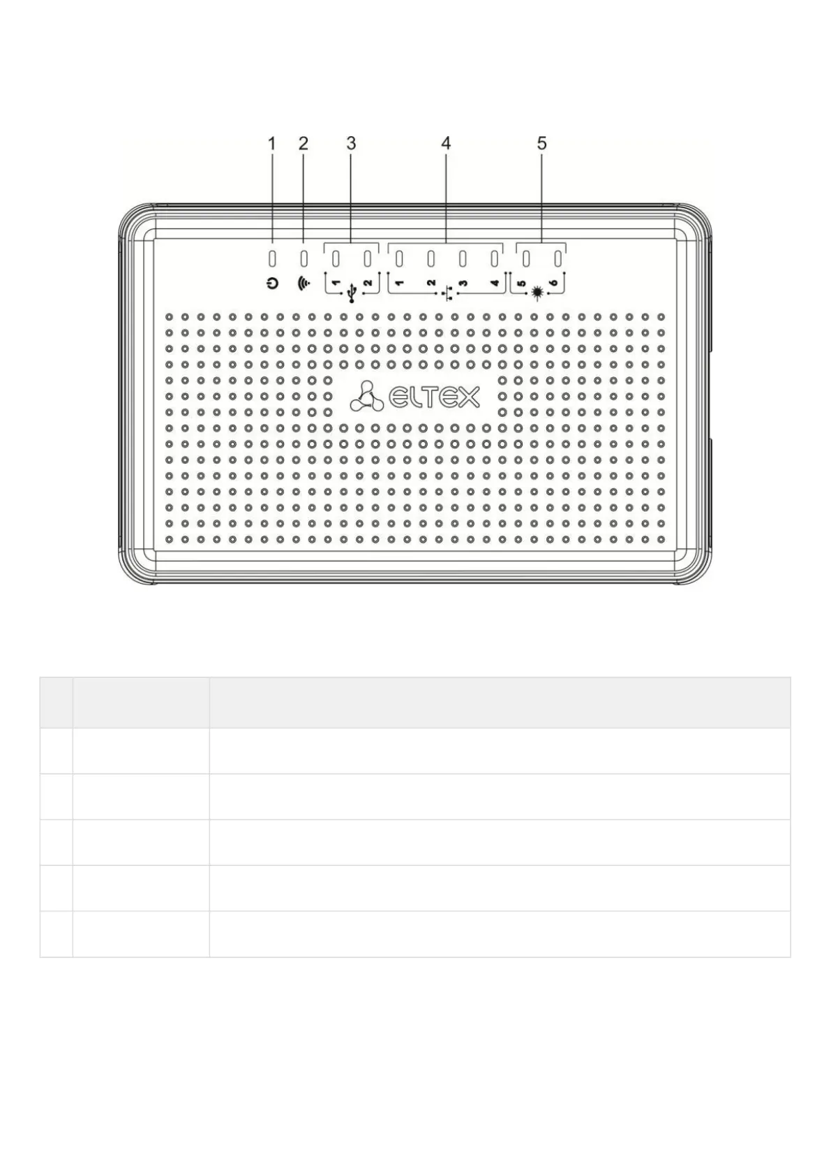
The top panel layout of ESR-10 is depicted in figure 49.
Figure 49 – ESR-10 top panel
Table 36 lists LEDs located on ESR-10 top panel.
Table 36 – Description of front panel LEDs
№ Top panel element Description
1 Power Device power and operation status LED.
2 - The LED is not used.
3 USB1, USB2 External USB devices LED.
4 [1 .. 4] Ethernet ports LED.
5 [5 .. 6] Optical interfaces LED.
 Loading...