EPSON Stylus COLOR 3000
EPSON Stylus Color 3000 Service Manual
A-2
Connector Pin Assignments
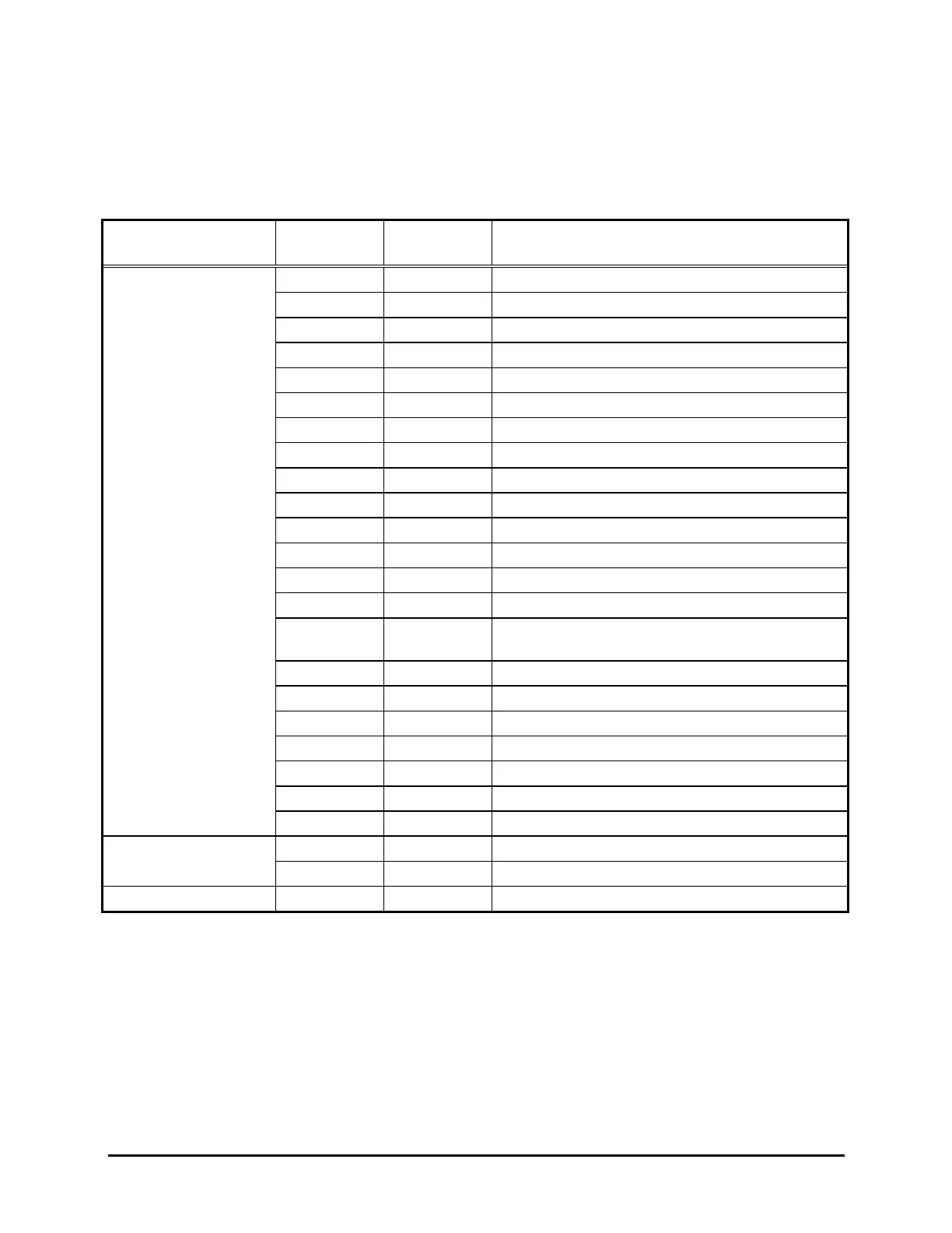
Table A-1 shows the locations and descriptions for the connectors on the circuit boards in this printer.
Tables A-2 to A-13 show the pin assignments for each connector.
Circuit Board
Connector
No.
Pin No. Description
C203 Main-B Board CN1 36 Parallel I/F (Refer to pages 1-16 to 1-20.)
CN2 36 Type-B I/F (Refer to pages 1-21 to 1-22.)
CN3 2 Release sensor
CN4 2 Front PE sensor
CN5 2 Rear PE sensor
CN6 3 HP sensor
CN7 4 Ink end/Cartridge sensor (Magenta)
CN8 5 ASF PW sensor
CN9 2 Platen gap sensor
CN10 3 ASF PQ sensor
CN11 6 ASF PL sensor
CN12 4 Ink end/Cartridge sensor (Yellow)
CN13 4 Ink end/Cartridge sensor (Cyan)
CN14 4 Ink end/Cartridge sensor (Black)
CN15 9 DC input from the C172 PSB/PSE board
Power off signal
CN16 8 Mac Serial I/F (Refer to pages 1-20 to 1-21.)
CN17 26 C203 PNL Board
CN18 24 Color printhead
CN20 4 Pump motor
CN21 26 Black printhead
CN22 5 CR motor
CN23 4 PF motor
C172 PSB/PSE Board CN1 2 AC power input
CN2 9 DC power input
C203 PNL Board CN1 26 To C203 Main-B board
Table A-1. Connector Summary

 Loading...


