Product Description
EPSON Stylus Color 3000 Service Manual
1-18
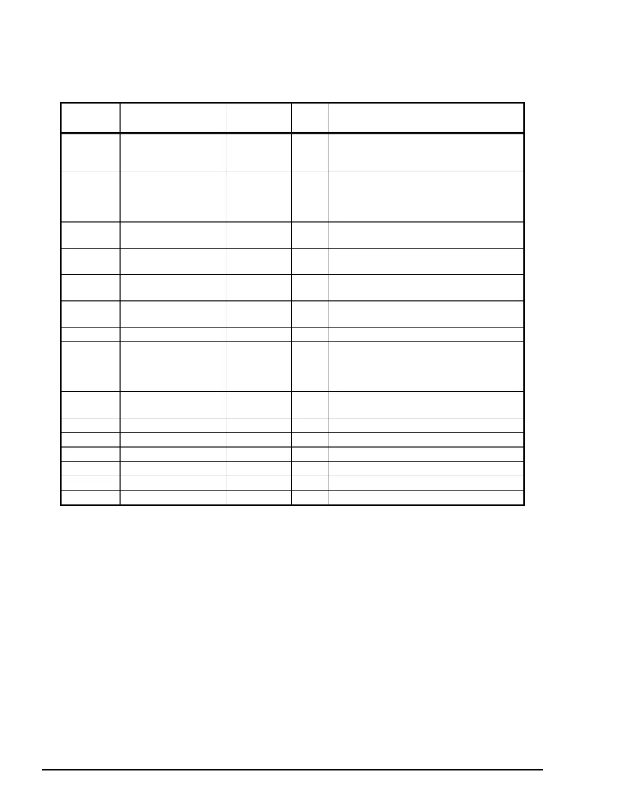
Table 1-21 shows the connector pin assignments and signals for the forward channel of the parallel interface.
Pin No. Signal Name
Return
GND Pin
I/O Description
1 /STROBE 19 I
The strobe pulse. Read-in of data is
performed at the falling edge of this
pulse.
2-9 DATA 0-7 20-27 I
The data 0 to data 7 signals represent
data bits 0 to 7, respectively. Each signal
is at a HIGH level when data is logical 1
and a LOW level when data is logical 0.
10 /ACKNLG 28 O
This signal is a negative pulse indicating
that the printer can again accept data.
11 BUSY 29 O
When this signal is at a HIGH level, the
printer is not ready to accept data.
12 PE 28 O
When this signal is at a HIGH level, the
paper empty status is detected.
13 SLCT 28 O
Always at a HIGH level when the printer
is powered on.
14 /AFXT 30 I Not used.
31 /INIT 30 I
The falling edge of a negative pulse or a
LOW signal on this line causes the printer
to initialize. Minimum 50 us pulse is
necessary.
32 /ERROR 29 O
When the printer detects an error, this
signal goes LOW.
36 /SLIN 30 I Not used.
18 Logic H - O Pulled up to +5V via 3.9 K-ohm resistor.
35 +5V - O Pulled up to +5V via 3.3 K-ohm resistor.
17 Chassis GND - - Chassis ground.
16,33,19-30 GND - - Signal ground.
15,34 NC - - Not connected.
Notes:
1. / at the beginning of a signal means active low.
2. The I/O column indicates the direction of the signal as viewed form the printer.
Table 1-21. Connector Pin Assignments and Signals (Forward Channel)

 Loading...


