5.
Enter fax mode by pushing fax button.
6.
Input fax number of PC on “ R” unit. (Regarding FAX number, refer to the
telephone
line
simulator
’
s
manual.)
7.
Push “ Start” button in “ B&W” mode.
8.
Push “ Back” button after being displayed as “ Send another page?” on LCD
panel to send fax data from “ R” unit to PC.
CHECK POINT OF “ R” UNIT
3.8.2.2
Fax Function Check by [Method B] and External
Connection Function Check
SETTING METHOD
Fax cable
CHECK PROCEDURE
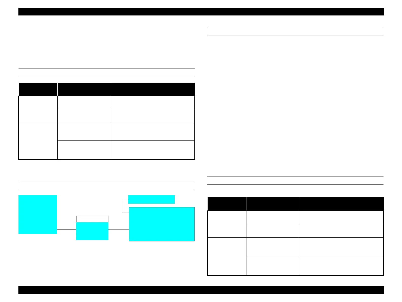
[Sender: “ R” unit => Receiver: “ G” unit]
1.
Set test chart on the document glass of “ R” unit.
2.
Enter fax mode by pushing fax button.
3.
Input fax number of “ G” unit on “ R” unit. (Regarding FAX number, refer
to
the
telephone
line
simulator
’
s
manual.)
4.
Push “ Start” button in “ B&W” mode.
5.
Push “ Back” button after being displayed as “ Send another page?” on LCD
panel to send fax data from “ R” unit to “ G” unit.
[Sender: “ G” unit => Receiver: “ R” unit]
1.
Set test chart on the document glass of “ G” unit.
2.
Enter fax mode by pushing fax button.
3.
Input fax number of “ R” unit on “ G” unit. (Regarding FAX number, refer to
the
telephone
line
simulator
’
s
manual.)
4.
Push “ Start” button in “ B&W” mode.
5.
Push “ Back” button after being displayed as “ Send another page?” on LCD
panel to send fax data from “ G” unit to “ R” unit.
6.
Confirm if telephone rings correctly during calling tone of “ R” unit rings.
7.
Confirm if dial tone of telephone is lost during “ R” unit receives fax data
without calling tone.
CHECK POINT OF “ R” UNIT
Fax cable
*Guaranteed unit means
FAX function and EXT
port perform correctly.
Guaranteed Epson Artisan
800/Epson Stylus Photo
PX800FW/TX800FW is
represented by “ G” unit
from this.
Fax cable
*Regarding FAX number,
refer to the telephone line
simulator
’
s
manual.
*Repaired/refurbished Epson Artisan
800/Epson Stylus Photo PX800FW/
TX800FW is represented by “ R” unit
from this.
*Refer to Table 3-37 on page 87 for
default setting.
 Loading...


