Epson Artisan 800/Epson Stylus Photo PX800FW/TX800FW/Epson Artisan 700/Epson Stylus Photo PX700W/TX700W
Disassembly Procedures
https://www.manualsbooks.com
4.2.2.2
Scanner Unit
6.
Release the hooks (x2) of the Hinge and hook (x1) of the ADF Cable Cover
from the rear side while holding the center of the ADF Unit. (See Fig. 4-5.)
7.
Remove the ADF Unit while pulling out the ADF Motor Cable, the ADF
Sensor Cable and the Grounding Wire from the hole of the Scanner Unit.
Figure 4-5. Removing the ADF Unit (2)
Parts/Components need to be removed in advance:
ADF Unit (Artisan 800/PX800FW/TX800FW only)
Removal procedure
1.
Open the Scanner Unit.
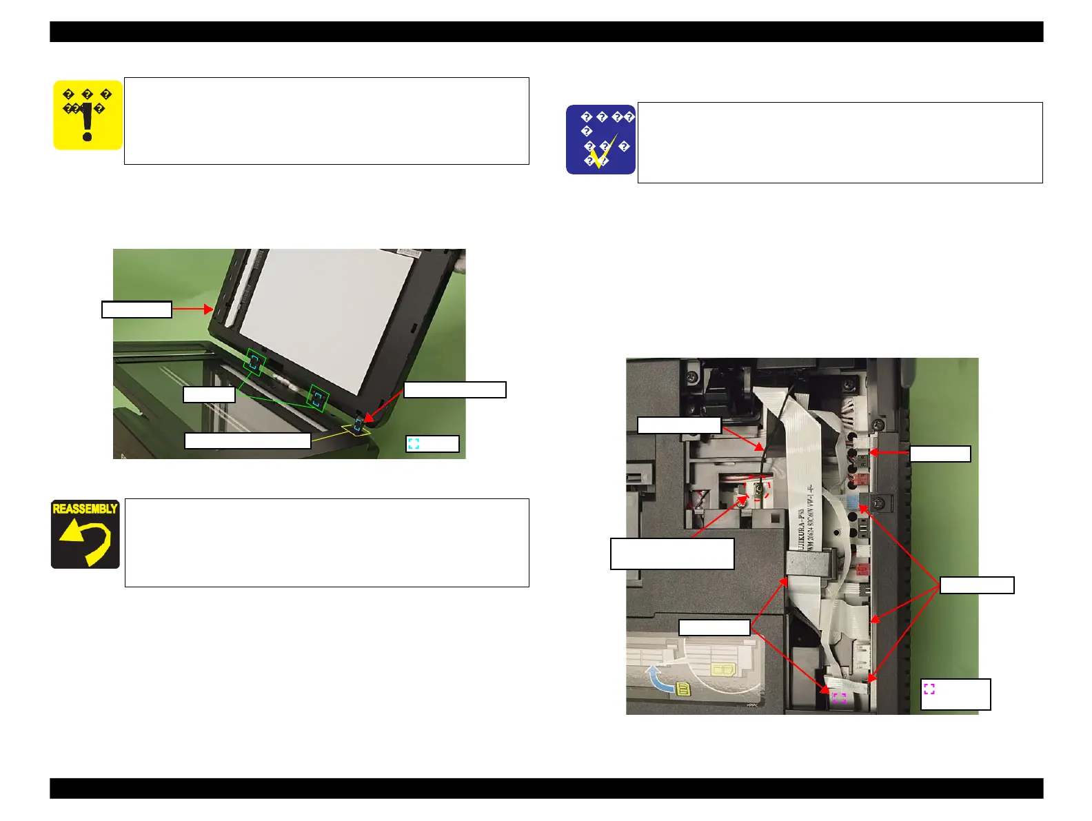
2.
Disconnect the Scanner FFCs (x3) together with the Ferrite Cores (x2) from
the Main Board. (See Fig. 4-6.)
3.
Pull out the terminal of the Grounding Wire from the fixing rib of the frame.
Figure 4-6. Removing the Scanner Unit (1)
Insert the terminal of the Grounding Wire to the end of the rib
of the Frame. (See Fig. 4-4.)
For routing cables, see 4.4 "Routing FFC/cables" (p202).
When installing the Cable Cover, secure it with a new Harness
Cover Clamp. (See Fig. 4-3.)
Take care not to let the cables get caught by the housing of the
Scanner Unit.
The disassembly/reassembly procedures of Artisan 700/PX700W/
TX700W differ from those of Artisan 800/PX800FW/TX800FW.
See 4.3.1.1 "Scanner Unit (Artisan 700/PX700W/TX700W)" (p185)
for the procedures.
Terminal of Grounding
Wire and the fixing rib
 Loading...


