Epson Artisan 800/Epson Stylus Photo PX800FW/TX800FW/Epson Artisan 700/Epson Stylus Photo PX700W/TX700W
Disassembly/reassembly procedures specific to Artisan 700/PX700W/TX700W
https://www.manualsbooks.com
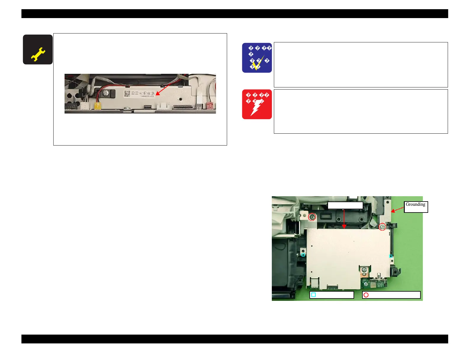
When replacing the Main Board, the MAC address need to be
set if the EEPROM data could not be read from the old Main
Board. In this case, attach the new “ Label, MAC address (Parts
number: 1489232)” to the position shown in Fig. 4-237 and
execute “ 5.2.6 "MAC Address Setting" (p223)”.
Figure 4-237. Position for the MAC Address Label
After removing/replacing the Main Board, make the specified
adjustments. (See Chapter 5 "ADJUSTMENT".)
4.3.2.3
Card Slot Assy (Artisan 700/PX700W/TX700W)
Parts/Components need to be removed in advance:
Scanner Unit/Upper Left Housing/Paper Guide Top Assy/
Upper Housing/Hinge/Rear Right Housing/Right Housing/Main Board Unit/
CSIC Assy/Cartridge Box Unit/Ink Supply Tube Assy
Removal procedure
1.
Remove the screws (x2) that secure the Card Slot Assy and remove the
Grounding Plate.
Figure 4-238. Removing the Card Slot Assy (1)
When powering this product, high-voltage current may be applied
on the SUB Board. To prevent ELECTRIC SHOCK, do not touch
the SUB Board section when the power is ON.
If the shock should happen, the flowing current is very tiny, about a
few hundreds A, therefore it will not do any harm on the human
body.
The disassembly/reassembly procedures for Artisan 800/
PX800FW/TX800FW differ from those of Artisan 700/
PX700W/TX700W, see 4.2.3.5 "Card Slot Assy" (p123) for the
procedures.
The Card Slot Assy includes the SUB Board and the STG
Board.
 Loading...


