Epson Artisan 800/Epson Stylus Photo PX800FW/TX800FW/Epson Artisan 700/Epson Stylus Photo PX700W/TX700W
Disassembly/reassembly procedures specific to Artisan 700/PX700W/TX700W
https://www.manualsbooks.com
Align the positioning holes (x2) on the Main Board with the
dowels (x2) of the Lower Shield Plate M/B. (See Fig. 4-234.)
Tighten the screws in the order given in Fig. 4-234.
Align the dowels (x2) of the Lower Shield Plate M/B with the
grooves (x2) of the Upper Shield Plate M/B. (See Fig. 4-233.)
Align the positioning holes (x2) of the Main Board Unit with the
dowels (x2) of the Base Frame. (See Fig. 4-232.)
Align the dowels (x2) of the Main Board Unit with the
positioning holes (x2) of the Right Cable Frame. (See Fig.
4-232.)
Insert the rib (x1) of the Grounding Plate M/B to the hole of the
Main Board Unit, and align the positioning hole (x1) of the
Grounding Plate M/B with the dowel (x1) of the Main Board
Unit, and attach the Grounding Plate M/B. (See Fig. 4-232,
Figure 4-235. Attaching the Grounding Plate M/B
When replacing the Grounding Plate Sheet M/B, insert the
sheet between the FFC and the Main Frame, and secure it with
double-sided tape to the Grounding Plate M/B. (See Fig. 4-230
When attaching the Ferrite Core Holder A, follow the
procedure below.
Align the dowels (x2) of the Main Board Unit with the
positioning holes (x2) of the Holder IC Shield Plate.
Secure the Ferrite Core Holder A and the Holder IC Shield
Plate to the Main Board Unit with the screw. (See Fig.
4-231.)
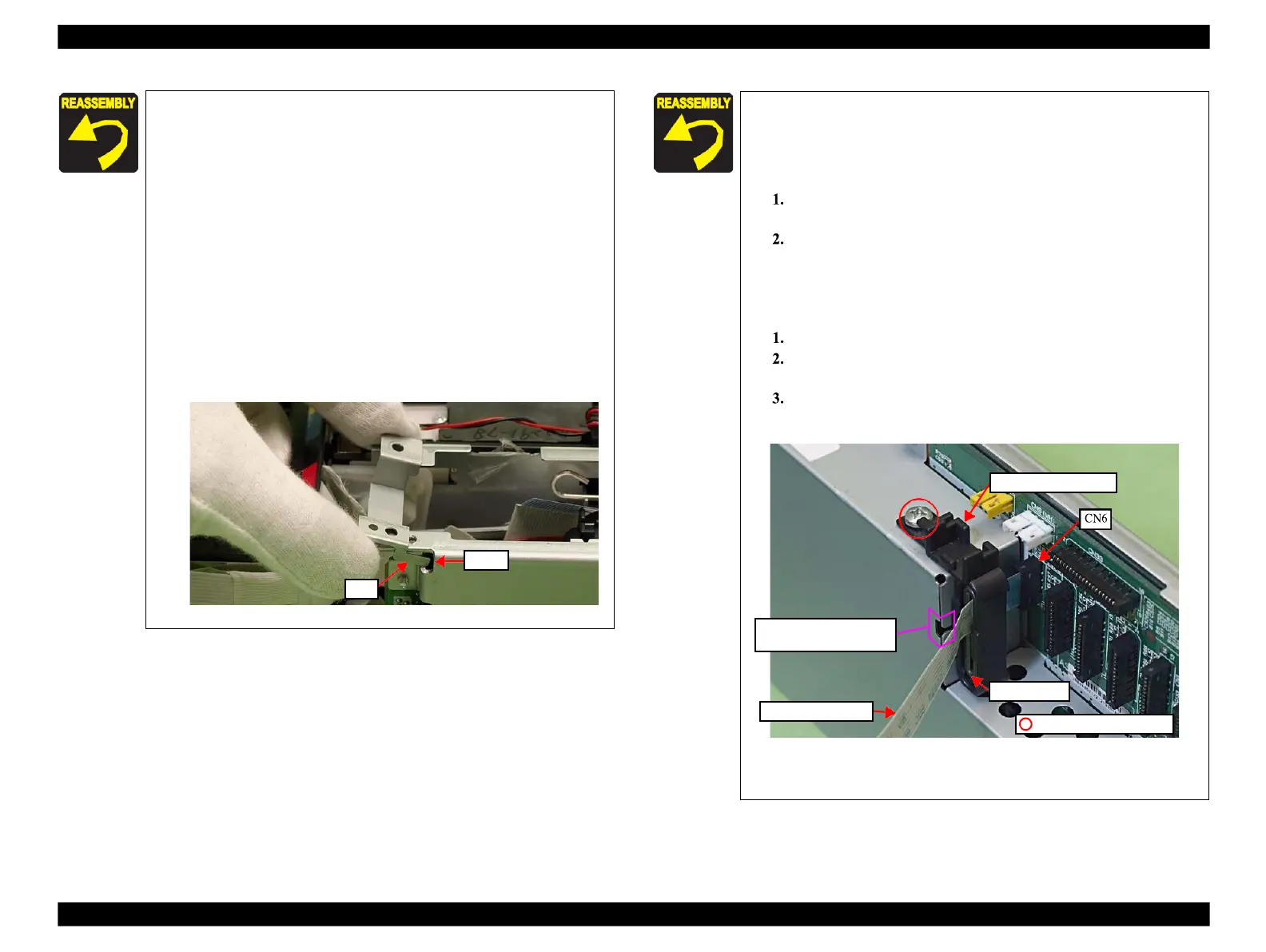
When attaching the CR Encoder FFC, follow the procedures
below.
Put the CR Encoder FFC through the ferrite core.
Connect the CR Encoder FFC to the connector (CN6) on
the Main Board.
Insert the rib of the Ferrite Core Holder B to the hole of the
Main Board, and secure it with the screw (x1).
Figure 4-236. Attaching the CR Encoder FFC
For routing the FFCs, see 4.4 "Routing FFC/cables" (p202).
Align and insert the rib of
the Ferrite Core Holder B
 Loading...


