Epson Artisan 800/Epson Stylus Photo PX800FW/TX800FW/Epson Artisan 700/Epson Stylus Photo PX700W/TX700W
Disassembly Procedures
https://www.manualsbooks.com
4.2.4.12
Front Frame
Parts/Components need to be removed in advance:
Main Frame
Removal procedure
1.
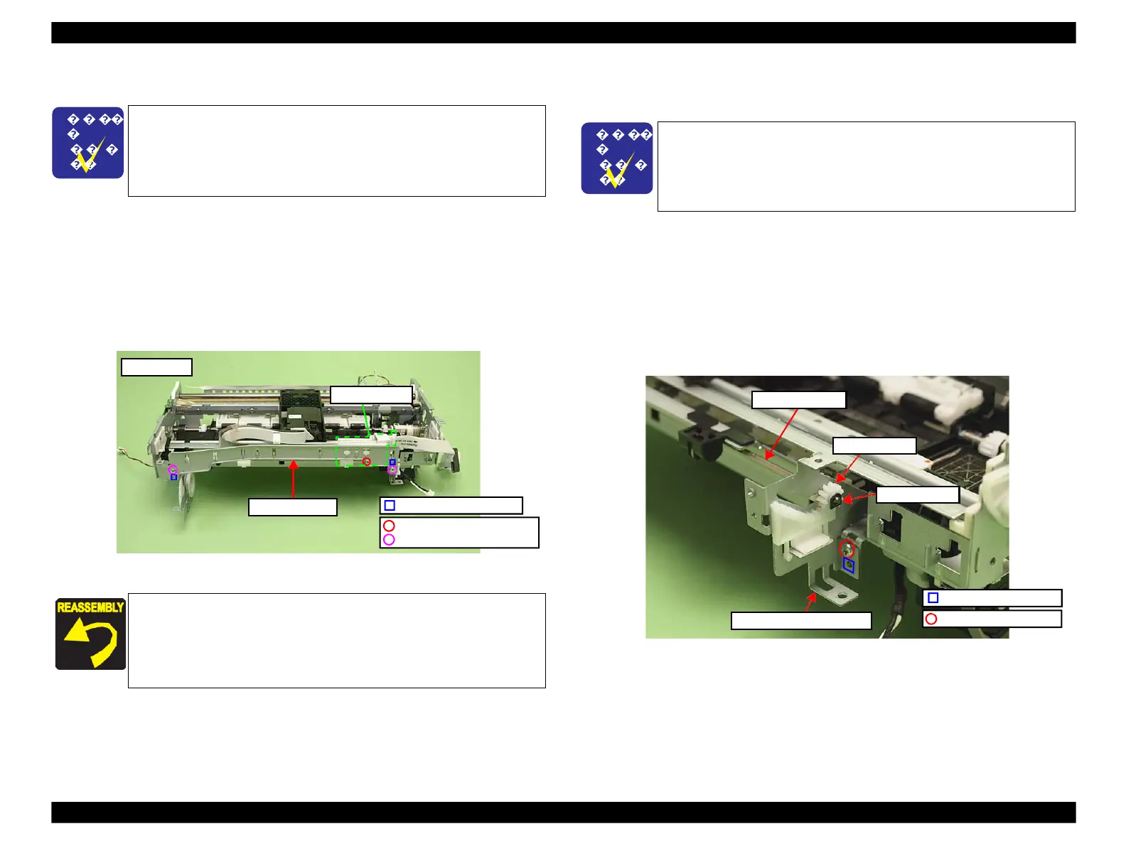
Remove the screw (x1) that secures the FFC Holder, and remove the FFC
Holder. (See Fig. 4-109.)
2.
Remove the screws (x2) that secure the Front Frame, and remove the Front
Frame.
Figure 4-109. Removing the Front Frame
4.2.4.13
EJ Frame Assy / EJ Release Frame Assy R/
EJ Release Frame Assy L
Parts/Components need to be removed in advance:
Main Frame/Front Frame
Removal procedure
1.
Remove the securing ring from the EJ Frame Shaft and remove the Spur Gear
A. (See Fig. 4-110.)
2.
Remove the screw (x1) that secures the EJ Release Frame Assy R, and
remove the EJ Release Frame Assy R.
Figure 4-110. Removing the EJ Release Frame Assy R
C.B.P. 3x8 (6±1Kgfcm)
C.B.S. 3x4 (8±1Kgfcm)
Align the positioning holes (x2) of the Front Frame with dowels (x2)
of the Main Frame. (See
The Main Frame becomes unstable once it is removed from the
Base Frame. Be careful not to deform the frame during
performing the following procedures.
◼
Refer to 4.2.4.11 Main Frame (p144) for the Parts/Components
need to be removed before removing the Main Frame.
The Main Frame becomes unstable once it is removed from the
Base Frame. Be careful not to deform the frame during
performing the following procedures.
◼
Refer to 4.2.4.11 Main Frame (p144) for the Parts/Components
need to be removed before removing the Main Frame.
 Loading...


