Epson Artisan 800/Epson Stylus Photo PX800FW/TX800FW/Epson Artisan 700/Epson Stylus Photo PX700W/TX700W
https://www.manualsbooks.com
3.2
Troubleshooting
3.2.1
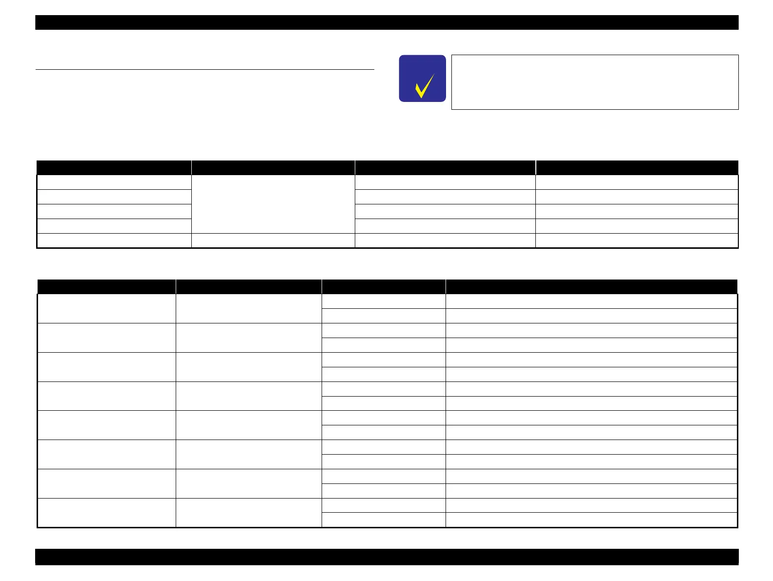
Motor and Sensor Troubleshooting
Motors
The resistance values for the CR motor and the PF motor are given below, however, the values cannot be used to check the motors status since they are DC motor and the resistance
between the electric poles varies. Visually check the motors for abnormal operation and if it is hard to judge, replace the motor.
Table 3-1. Motor resistance and check point
Main Board: Pin1-Pin2 of CN21
Main Board: Pin1-Pin2 of CN22
Main Board: Pin1-Pin2 of CN24
Main Board: Pin1-Pin2 of CN49
4-phase, 96-pole PM stepping motor
Main Board: Pin1-Pin3, Pin2-Pin4 of CN25
28.0
± 7 %/phase (25
o
C)
Sensors
Table 3-2. Sensor check point
PE Sensor
(Transmissive photo interrupter)
Main Board: Pin1-Pin2 of CN9
Scanner Cover Open Sensor (1)
(GMR sensor)
Main Board: Pin1-Pin2 of CN10
Scanner Cover Open Sensor (2)
(GMR sensor)
Main Board: Pin2-Pin4 of CN10
Carriage: at the origin position (where the carriage touches the right frame)
PW Sensor
(Reflective photo interrupter)
Main Board: Pin1-Pin3 of CN6
3.3 V (for reference only)
Duplex Unit Sensor
(Mechanical contact points)
Main Board: Pin1-Pin2 of CN13
CDR Tray Sensor
(Mechanical contact points)
Main Board: Pin1-Pin2 of CN14
Photo Tray Sensor
(Mechanical contact points)
Main Board: Pin1-Pin2 of CN12
EJ Cover Open Sensor
(Electromagnetic plunger)
Main Board: Pin1-Pin2 of CN19
For the position of each sensor/motor, see 2.1.3 " Motors & Sensors "
(p.49).
TROUBLESHOOTING Troubleshooting 55
 Loading...


