Epson Artisan 800/Epson Stylus Photo PX800FW/TX800FW/Epson Artisan 700/Epson Stylus Photo PX700W/TX700W
Disassembly/reassembly procedures specific to Artisan 700/PX700W/TX700W
https://www.manualsbooks.com
4.3.1.2
Upper Left Housing (Artisan 700/PX700W/TX700W)
Parts/Components need to be removed in advance:
None
Removal procedure
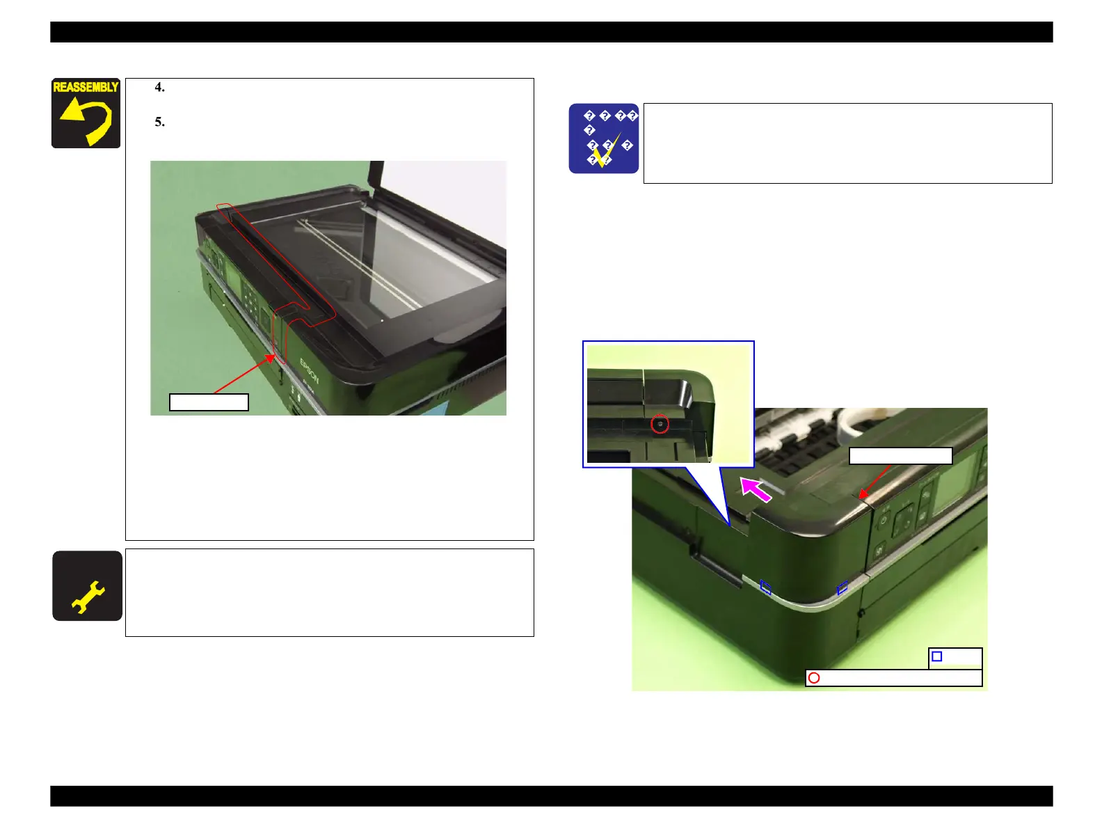
1.
Remove the screw (x1) that secures the Upper Left Housing.
2.
Slide the Upper Left Housing to the rear side, release the hooks (x2) and
remove the Upper Left Housing.
Figure 4-209. Removing the Upper Left Housing
Close the Scanner Unit while temporarily tightening them
screw (x1).
Tighten the screw (x1) after making sure that there is no
gap between the Scanner Unit and the printer.
Figure 4-208. Installing the Scanner Unit (2)
Make sure to insert the terminal of the Grounding wire to the
fixing rib of the frame. (See Fig. 4-204.)
For the routing the FFCs, see
4.4 "Routing FFC/cables" (p202).
When installing the Cable Cover, secure it with a new Harness
Cover Clamp. (See Fig. 4-203.)
The disassembly/reassembly procedures for Artisan 800/PX800FW/
TX800FW differ from those of Artisan 700/PX700W/TX700W, see
4.2.2.4 "Upper Left Housing / Panel Lock Button" (p106) for the
procedures.
After removing/replacing the Scanner Unit, make the specified
adjustments. (See Chapter 5 "ADJUSTMENT".)
C.B.P. 3x10 (black) (6±1Kgfcm)
 Loading...


