Epson Artisan 800/Epson Stylus Photo PX800FW/TX800FW/Epson Artisan 700/Epson Stylus Photo PX700W/TX700W
Disassembly Procedures
https://www.manualsbooks.com
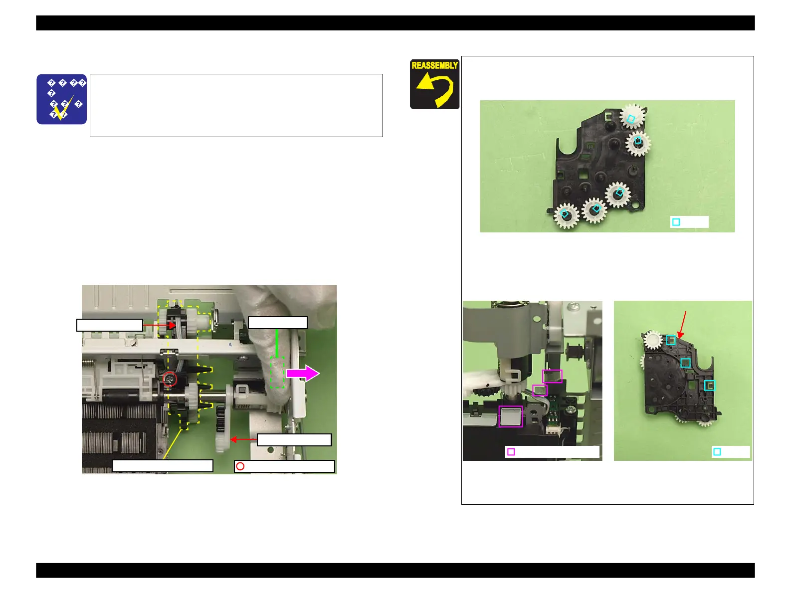
Make sure that all gears on the Transmission Holder Assy are
properly installed to the hooks and move smoothly.
Figure 4-141. Installing the Transmission Holder Assy (1)
When assembling the Transmission Holder Assy, align the
hooks (x3) of the Transmission Holder Assy with the ribs (x3)
of the Main Frame.
Figure 4-142. Installing the Transmission Holder Assy (2)
For routing the FFCs, see 4.4 "Routing FFC/cables" (p202).
4.2.4.17
Transmission Holder Assy
Parts/Components need to be removed in advance:
Main Frame/Printhead/CR Scale/Carriage Unit/Ink System
Removal procedure
1.
Push the Switch Lever in the direction of the arrow and disengage the
Transmission Arm from the Transmission Holder Assy. (See Fig. 4-86, Fig.
4-140.)
2.
Remove the screw (x1) that secures the Transmission Holder Assy. (See Fig.
4-140.)
3.
Release the PE Sensor Cable from the Transmission Holder Assy, and remove
the Transmission Holder Assy.
Figure 4-140. Removing the Transmission Holder Assy
The Main Frame becomes unstable once it is removed from the
Base Frame. Be careful not to deform the frame during
performing the following procedures.
◼
Refer to 4.2.4.11 Main Frame (p144) for the Parts/Components
need to be removed before removing the Main Frame.
 Loading...


