Epson Artisan 800/Epson Stylus Photo PX800FW/TX800FW/Epson Artisan 700/Epson Stylus Photo PX700W/TX700W
Disassembly/reassembly procedures specific to Artisan 700/PX700W/TX700W
https://www.manualsbooks.com
2.
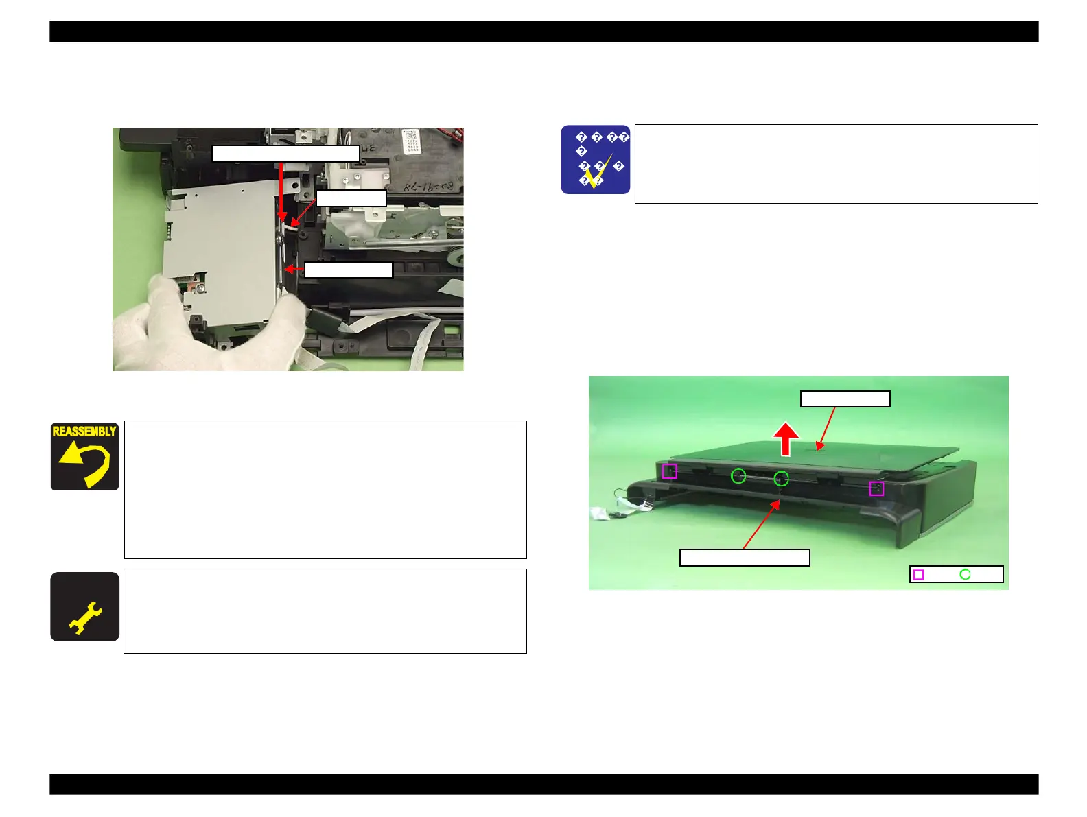
Disconnect the AID cable from the connector on the SUB Board, and remove
the Card Slot Assy.
Figure 4-239. Removing the Card Slot Assy (2)
4.3.3
Disassembling the Scanner Unit (Artisan 700/
PX700W/TX700W)
4.3.3.1
Document Cover
Parts/Components need to be removed in advance:
Scanner Unit/ADF Unit
Removal procedure
1.
Release the dowels (x2) and ribs (x2) of the Document Cover with the
Document Cover closed, and remove the Document Cover from the Scanner
Upper Housing in the direction of the arrow.
Figure 4-240. Removing the Document Cover
Connect the AID cable properly to the connector on the SUB
Board. (See Fig. 4-239.)
Align the grooves (x2) of the Card Slot Assy with the dowels (x2)
of the Base Frame. (See Fig. 4-238.)
When attaching the Grounding Plate, install it over the Card
Slot Assy, and tighten them together with the screw. (See Fig.
4-238.)
For routing the FFCs, see 4.4 "Routing FFC/cables" (p202).
After removing/replacing the Card Slot Assy, make the specified
adjustments. (See Chapter 5 "ADJUSTMENT".)
Connector on the SUB Board
The disassembly/reassembly procedures for Artisan 800/PX800FW/
TX800FW differ from those of Artisan 700/PX700W/TX700W, see
4.2.5 "Disassembling Scanner Unit" (p167) for the procedures.
 Loading...


