Epson Artisan 800/Epson Stylus Photo PX800FW/TX800FW/Epson Artisan 700/Epson Stylus Photo PX700W/TX700W
Disassembly Procedures
https://www.manualsbooks.com
4.2.2.12 Cassette
Unit (p114)
4.2.2.10 Rear Right
FAX Housing (p112)
4.2.4.21 Lower Paper
Guide Waste Ink Pad
Assy (p165)
4.2.3.3 Power Supply
Unit (p121)
4.2.2.11 Right Housing /
Card Cover (p113)
4.2.4.22 Front Paper
Guide Waste Ink Pad
(p166)
4.2.2.9 Rear ASF Paper
Guide Cover (p111)
4.2.3.2 Main Board /
Grounding Plate M/B
(p117)
4.2.3.4 Wireless LAN
Board (p122)
4.2.4.7 Lower ASF Paper
Guide Assy (p138)
4.2.4.3 Decompression 4.2.3.4 Wireless LAN
Pump Unit (p130) Board (p122)
4.2.4.9 LD Roller (p142) 4.2.4.8 CDR Tray Assy
(p140)
4.2.4.20 Waste Ink Tray
Assy (p163)
4.2.3.5 Card Slot Assy
(p123)
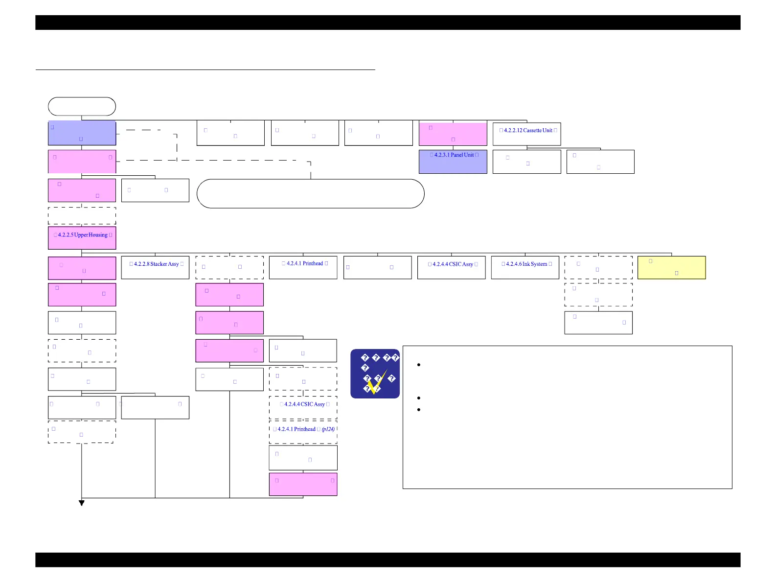
The colored blocks indicate the following.
Red: Basically the disassembling procedures are in common with both
Artisan 800/PX800FW/TX800FW and Artisan 700/PX700W/
TX700W, but some parts differ in shape.
Blue: Artisan 800/PX800FW/TX800FW only.
Yellow: Artisan 700/PX700W/TX700W only.
The parts surrounded with dotted line are not the shortest ways of
removing them, but you need to remove the parts/units if they exist on the
way to the target part/unit.
When replacing the printer mechanism, see
4.2.1 "Parts transferred from
the old printer when replacing the Printer Mechanism" (p101)
to transfer
the parts from the old printer to the new one.
4.2
Disassembly Procedures
For disassembling each unit, refer to the pages in the following flowchart.
“
4.2.2.13 Paper Guide
Top Assy
”
(p115)
Flowchart 4-2 Disassembling Flowchart (2) (p100)
Flowchart 4-1. Disassembling Flowchart (1)
4.2.4.10 Pick-up
Roller (p143)
(p115)(Artisan 800/
PX800FW/TX800FW)
(p103)
4.2.2.4 Upper Left
Housing / Panel Lock
4.2.2.13 Paper Guide
Top Assy (p115)
4.2.2.1 ADF Unit (Artisan
800/PX800FW/TX800FW
only) (p102)
See Flowchart 4-2 Disassembling Flowchart (2) (p100) for
disassembling procedures of the Scanner Unit and the ADF Unit.
 Loading...


