4.2.2.13
Paper Guide Top Assy
Parts/Components need to be removed in advance:
None
Removal procedure
1.
Open the Scanner Unit.
2.
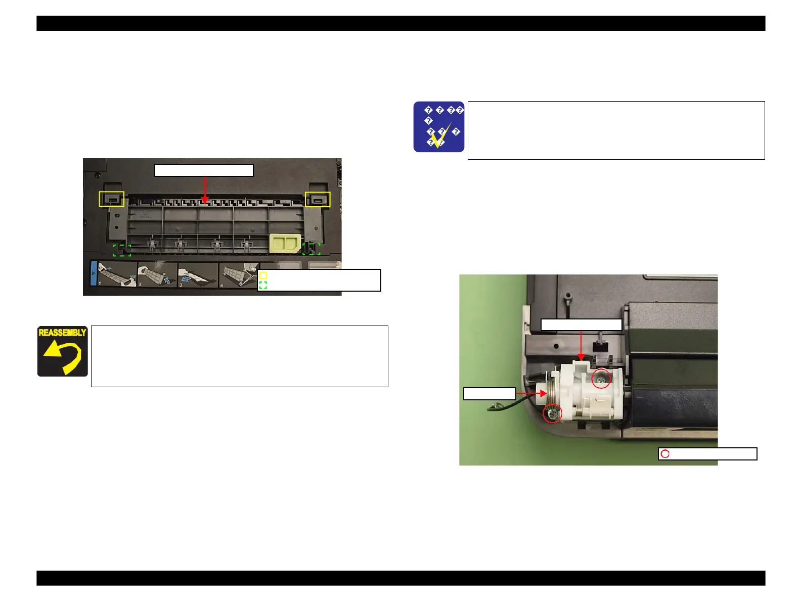
Release the hooks (x2) and remove the Paper Guide Top Assy.
Figure 4-34. Removing the Paper Guide Top Assy
4.2.3
Removing the Circuit Board
4.2.3.1
Panel Unit
Parts/Components need to be removed in advance:
Upper Left Housing
Removal procedure
1.
Remove the Grounding Wire. (See 4.2.2.5 Upper Housing Step1 (p107).)
2.Remove the Panel Spring (x1). (See Fig. 4-35.)
3.
Remove the screws (x2) that secure the Ratchet Holder Assy.
Figure 4-35. Removing the Ratchet Holder Assy (1)
Align and insert the dowels (x2) of the Paper Guide Top Assy to the
grooves of the Housing, and secure it with the hooks (x2). (See Fig.
4-34.)
The disassembly/reassembly procedures of Artisan 700/PX700W/
TX700W differ from those of Artisan 800/PX800FW/TX800FW.
See 4.3.2.1 "Panel Unit (Artisan 700/PX700W/TX700W)" (p194) for
the procedures.
 Loading...


