4.
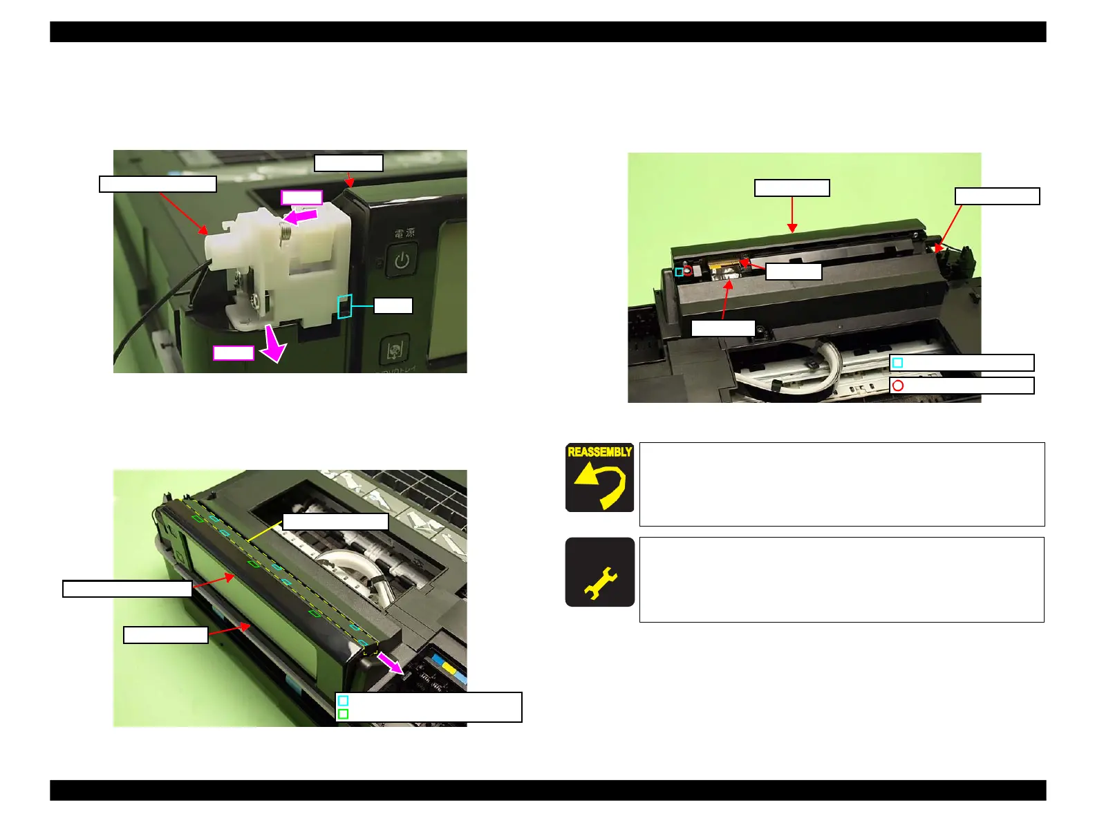
Slide the Ratchet Holder Assy to the left, and release the rib A. (See Fig.
4-36.)
5.
Slide the Ratchet Holder Assy to the front to remove it from the Upper
Housing, and remove it from the Panel Unit.
Figure 4-36. Removing the Ratchet Holder Assy (2)
6.
Release the hooks (x3) of the Front Panel Unit Cover. (See Fig. 4-37.)
7.
Slide the Upper Panel Cover in the direction of the arrow to release the hooks
(x6), and remove the Upper Panel Cover.
Figure 4-37. Removing the Panel Unit (1)
8.
Disconnect the Panel FFC from the connector of the Panel Unit. (See Fig.
4-38.)
9.
Remove the screw (x1) that secures the Panel Unit and remove the Panel Unit
from the Upper Housing.
Figure 4-38. Removing the Panel Unit (2)
Align and insert the dowel of the Right Hinge to the positioning
hole of the Panel Unit. (See Fig. 4-38.)
Insert the rib A of the Ratchet Holder Assy to the position
shown in Fig. 4-36. (See Fig. 4-36.)
After removing/replacing the Panel Unit, make the specified
adjustments. (See Chapter 5 "ADJUSTMENT".)
 Loading...


