Epson Artisan 800/Epson Stylus Photo PX800FW/TX800FW/Epson Artisan 700/Epson Stylus Photo PX700W/TX700W
Disassembly Procedures
https://www.manualsbooks.com
4.2.5.2
Scanner Motor Unit
Parts/Components need to be removed in advance:
Scanner Unit/ADF Unit/Scanner Upper Housing
Removal procedure
1.
Disconnect the Scanner Motor cable from the connector (CN2) on the Scanner
CR Encoder Board.
2.
Remove the screws (x3) that secure the Scanner Motor Unit and remove the
Scanner Motor Unit from the Scanner Lower Housing.
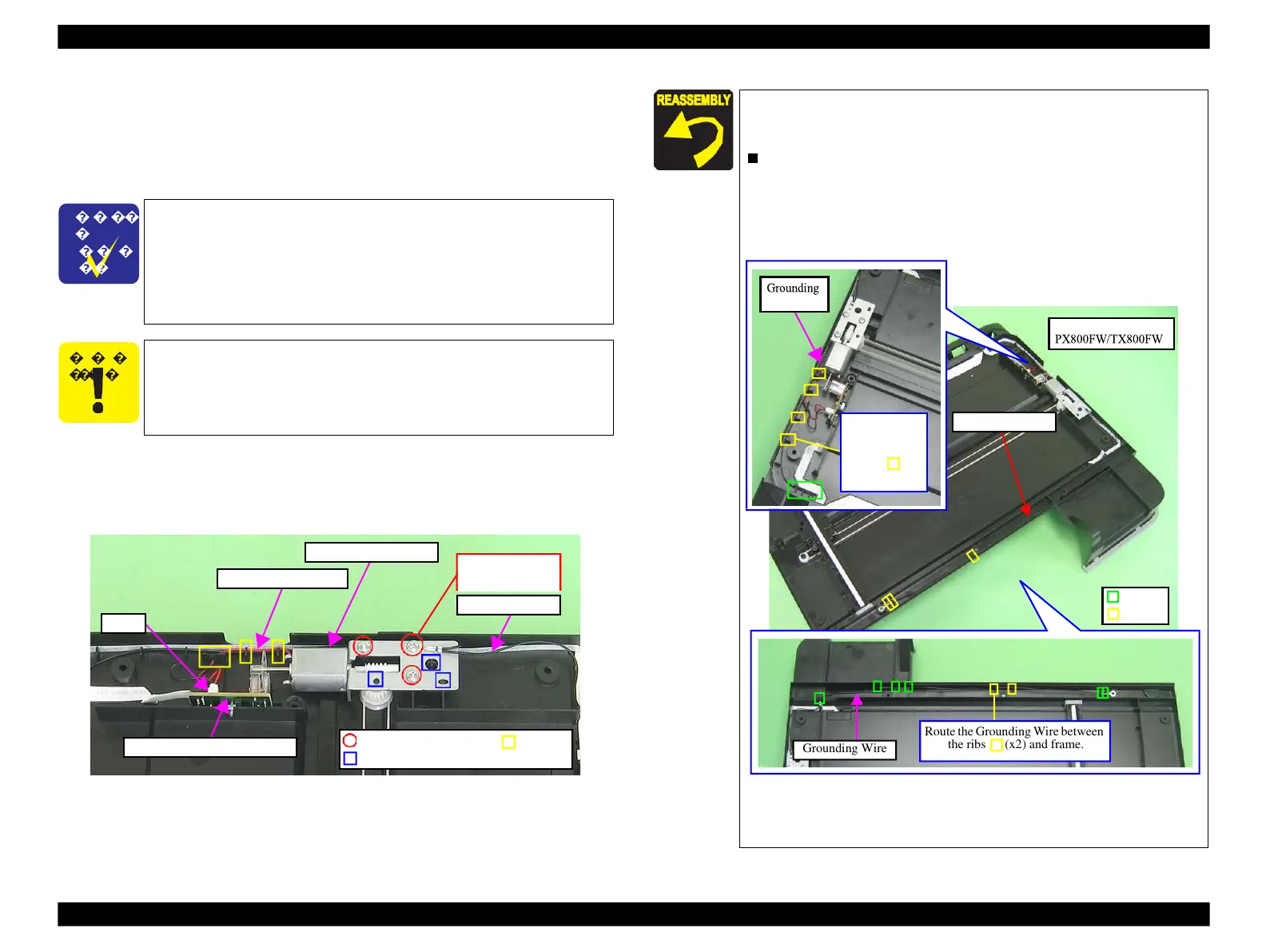
Figure 4-164. Removing the Scanner Motor Unit
Route the Grounding Wire between
the ribs (x2) and frame.
When installing the Scanner Motor Unit, be sure of the following.
Route the Scanner Motor cable through the grooves (x3) of the
Scanner Lower Housing. (See Fig. 4-164.)
Align the positioning holes (x3) of the Scanner Motor Unit with
the dowels (x3) of the Scanner Lower Housing. (See Fig. 4-164
Route the Grounding Wire as shown below and in Fig. 4-171.
(Artisan 800/PX800FW/TX800FW: Fig. 4-165, Artisan 700/
PX700W/TX700W: Fig. 4-166.)
Figure 4-165. Routing the Grounding Wire
(Artisan 800/PX800FW/TX800FW)
(Continued to the next page.)
Wire between
the ribs (x5)
Some of the parts of Artisan 800/PX800FW/TX800FW differ from
those of Artisan 700/PX700W/TX700W.
Unless otherwise specified, this section describes the procedures for
Artisan 800/PX800FW/TX800FW. The differences that may affect
the disassembly/reassembly procedures of Artisan 700/PX700W/
TX700W will be provided in “ Reassembly” , etc.
Be sure of the following.
Be careful not to touch the Scanner CR Scale with bare hands.
Be careful not to damage the Scanner CR Scale.
Screw it with the
Grounding Wire
C.B.P.,3x8 (5±1kgfcm) Groove
Positioning hole & dowel
 Loading...


